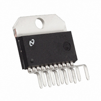
LM2984T/NOPB National Semiconductor, LM2984T/NOPB Datasheet - Page 16

LM2984T/NOPB
Manufacturer Part Number
LM2984T/NOPB
Description
IC CONV MICROPROCESSOR TO220-11
Manufacturer
National Semiconductor
Datasheet
1.LM2984TNOPB.pdf
(20 pages)
Specifications of LM2984T/NOPB
Applications
Converter, Microprocessor
Voltage - Input
6 ~ 26 V
Number Of Outputs
3
Voltage - Output
5V
Operating Temperature
-40°C ~ 125°C
Mounting Type
Through Hole
Package / Case
TO-220-11 (Bent and Staggered Leads)
Lead Free Status / RoHS Status
Contains lead / RoHS non-compliant
Other names
*LM2984T
*LM2984T/NOPB
LM2984T
*LM2984T/NOPB
LM2984T
www.national.com
The delayed RESET will be initiated any time the main output
is out of regulation, i.e. during power-up, short circuit, over-
voltage, low line, thermal shutdown or power-down. The μP
is therefore RESET whenever the output voltage is out of
regulation. (It is important to note that a RESET is only initi-
ated when the main output is in error. The buffer and standby
outputs are not directly monitored for error conditions.)
μP MONITOR RESET
There are two distinct and independent error monitoring sys-
tems in the LM2984. The one described above monitors the
main regulator output and initiates a delayed RESET when-
ever this output is in error. The other error monitoring system
is the μP watchdog. These two systems are OR'd together
internally and both force the RESET output low when either
type of error occurs.
This watchdog circuitry continuously monitors a pin on the
μP that generates a positive going pulse during normal oper-
ation. The period of this pulse is typically on the order of
milliseconds and the pulse width is typically on the order of
10's of microseconds. If this pulse ever disappears, the watch-
dog circuitry will time out and a RESET low will be sent to the
μP. The time out period is determined by two external com-
ponents, R
The width of the RESET pulse is set by C
resistor according to the following:
A square wave signal can also be monitored for errors by fil-
tering the C
t
mon
and C
RESET
T
input such that only the positive edges of the
window
T
mon
dly
pw
, according to the formula:
= 0.82 R
= 1.2 R
= 2000 C
t
C
t
C
t
mon
(seconds)
mon
(seconds)
(seconds)
mon
and an internal
16
signal are detected. Figure 2 is a schematic diagram of a typ-
ical circuit used to differentiate the input signal. Resistor R
and capacitor C
and create a short positive pulse suitable for the μP monitor
input. If the incoming signal continues in a high state or in a
low state for too long a period of time, a RESET low will be
generated.
The threshold voltage and input characteristics of this pin are
compatible with nearly all logic families.
There is a limit on the width of a pulse that can be reliably
detected by the watchdog circuit. This is due to the output
resistance of the transistor which discharges C
high state is detected at the input. The minimum detectable
pulse width can be determined by the following formula:
FIGURE 2. Monitoring Square Wave μP Signals
tc
PW
pass only the rising edge of the square wave
min
= 20 C
mon
(seconds)
mon
1125214
when a
tc


