LM2597M-5.0/NOPB National Semiconductor, LM2597M-5.0/NOPB Datasheet - Page 4
LM2597M-5.0/NOPB
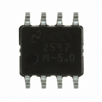
Manufacturer Part Number
LM2597M-5.0/NOPB
Description
IC REG SIMPLE SWITCHER 8-SOIC
Manufacturer
National Semiconductor
Series
SIMPLE SWITCHER®r
Type
Step-Down (Buck)r
Datasheet
1.LM2597M-3.3NOPB.pdf
(34 pages)
Specifications of LM2597M-5.0/NOPB
Internal Switch(s)
Yes
Synchronous Rectifier
No
Number Of Outputs
1
Voltage - Output
5V
Current - Output
500mA
Frequency - Switching
150kHz
Voltage - Input
4.5 ~ 40 V
Operating Temperature
-40°C ~ 125°C
Mounting Type
Surface Mount
Package / Case
8-SOIC (3.9mm Width)
Primary Input Voltage
12V
No. Of Outputs
1
Output Voltage
5V
Output Current
500mA
No. Of Pins
8
Operating Temperature Range
-40°C To +125°C
Supply Voltage Range
4.5V To 40V
Filter Terminals
SMD
Rohs Compliant
Yes
Input Voltage Primary Max
40V
Lead Free Status / RoHS Status
Lead free / RoHS Compliant
Power - Output
-
Other names
*LM2597M-5.0
*LM2597M-5.0/NOPB
LM2597M-5.0
*LM2597M-5.0/NOPB
LM2597M-5.0
Available stocks
Company
Part Number
Manufacturer
Quantity
Price

Part Number:
LM2597M-5.0/NOPB
Manufacturer:
TI/德州仪器
Quantity:
20 000


www.national.com
Symbol
DEVICE PARAMETERS
I
SHUTDOWN/SOFT-START CONTROL Test Circuit of Figure 12
V
V
I
I
FLAG/DELAY CONTROL Test Circuit of Figure 12
VF
IF
BIAS SUPPLY
I
I
STBY
SD
SS
BS
Q
All Output Voltage Versions
Electrical Characteristics
JA
Specifications with standard type face are for T
ture Range. Unless otherwise specified, V
sion. I
SD
SS
Note 1: Absolute Maximum Ratings indicate limits beyond which damage to the device may occur. Operating Ratings indicate conditions for which the device is
intended to be functional, but do not guarantee specific performance limits. For guaranteed specifications and test conditions, see the Electrical Characteristics.
Note 2: Voltage internally clamped. If clamp voltage is exceeded, limit current to a maximum of 1 mA.
Note 3: The human body model is a 100 pF capacitor discharged through a 1.5k resistor into each pin.
Note 4: Typical numbers are at 25˚C and represent the most likely norm.
L
SAT
LOAD
Current
Standby Quiescent
Current
Thermal Resistance
Shutdown Threshold
Voltage
Soft-start Voltage
Shutdown Current
Soft-start Current
Regulator Dropout
Detector
Threshold Voltage
Flag Output Saturation
Voltage
Flag Output Leakage
Current
Delay Pin Threshold
Voltage
Delay Pin Source
Current
Delay Pin Saturation
Bias Supply Pin Current
Operating Quiescent
Current
= 100 mA.
Parameter
SD /SS pin = 0V
N Package, Junction to Ambient (Note 12)
M Package, Junction to Ambient (Note 12)
Low, (Shutdown Mode)
High, (Soft-start Mode)
V
V
V
V
Low (Flag ON)
I
V
V
Low (Flag ON)
High (Flag OFF) and V
V
Low (Flag ON)
V
V
V
SINK
OUT
OUT
SHUTDOWN
Soft-start
DELAY
FLAG
DELAY
BS
BS
BS
IN
(Continued)
= 2V
= 4.4V (Note 10)
= 4.4V , V
= 3 mA
= 12V for the 3.3V, 5V, and Adjustable version and V
= 20% of Nominal Output Voltage
= 100% of Nominal Output Voltage
= 40V
J
= 0.5V
= 0.5V
= 2.5V
= 25˚C, and those with boldface type apply over full Operating Tempera-
= 0.5V
in
(Note 10)
Conditions
pin current(Note 10)
LM2597HV
OUT
4
(Note 10)LM2597
Regulated
LM2597/LM2597HV-XX
(Note 4)
1.25
Typ
140
150
120
1.3
1.6
0.3
0.3
85
95
96
55
2
3
5
3
4
1
IN
= 24V for the 12V ver-
(Note 5)
200/250
250/300
350/400
0.7/1.0
Limit
1.21
1.29
400
0.6
10
10
92
98
10
2
5
6
2
mA(max)
mV(max)
mA(max)
µA(max)
µA(max)
µA(max)
µA(max)
µA(max)
µA(max)
(Limits)
%(max)
V(max)
%(min)
V(max)
V(max)
V(min)
V(min)
Units
˚C/W
mV
mA
mA
µA
µA
µA
µA
µA
µA
%
V
V
V
V
Related parts for LM2597M-5.0/NOPB
Image
Part Number
Description
Manufacturer
Datasheet
Request
R

Part Number:
Description:
IC REG SIMPLE SWITCHER 8-SOIC
Manufacturer:
National Semiconductor
Datasheet:

Part Number:
Description:
IC REG SIMPLE SWITCHER 8-SOIC
Manufacturer:
National Semiconductor
Datasheet:

Part Number:
Description:
IC REG SIMPLE SWITCHER 8-SOIC
Manufacturer:
National Semiconductor
Datasheet:

Part Number:
Description:
SWITCHING REG 0.5A 5.0V, SMD, 2597
Manufacturer:
National Semiconductor
Datasheet:
Part Number:
Description:
SWITCHING REG 0.5A ADJ, SMD, 2597
Manufacturer:
National Semiconductor
Datasheet:

Part Number:
Description:
IC, STEP-DOWN REGULATOR, 8-SOIC
Manufacturer:
National Semiconductor
Datasheet:
Part Number:
Description:
IC, STEP-DOWN REGULATOR, 8-SOIC
Manufacturer:
National Semiconductor
Datasheet:
Part Number:
Description:
National Semiconductor [8-Bit D/A Converter]
Manufacturer:
National Semiconductor
Datasheet:
Part Number:
Description:
National Semiconductor [Media Coprocessor]
Manufacturer:
National Semiconductor
Datasheet:
Part Number:
Description:
Digitally Controlled Tone and Volume Circuit with Stereo Audio Power Amplifier, Microphone Preamp Stage and National 3D Sound
Manufacturer:
National Semiconductor
Datasheet:
Part Number:
Description:
Digitally Controlled Tone and Volume Circuit with Stereo Audio Power Amplifier, Microphone Preamp Stage and National 3D Sound
Manufacturer:
National Semiconductor
Datasheet:
Part Number:
Description:
AC97 Rev 2 Codec with Sample Rate Conversion and National 3D Sound
Manufacturer:
National Semiconductor
Part Number:
Description:
Manufacturer:
National Semiconductor
Datasheet:
Part Number:
Description:
Manufacturer:
National Semiconductor
Datasheet: