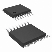
LM26400YMH/NOPB National Semiconductor, LM26400YMH/NOPB Datasheet - Page 15

LM26400YMH/NOPB
Manufacturer Part Number
LM26400YMH/NOPB
Description
IC REG BUCK DUAL 2A 16-ETSSOP
Manufacturer
National Semiconductor
Type
Step-Down (Buck)r
Datasheet
1.LM26400YSDNOPB.pdf
(24 pages)
Specifications of LM26400YMH/NOPB
Internal Switch(s)
Yes
Synchronous Rectifier
No
Number Of Outputs
2
Voltage - Output
0.6 ~ 16 V
Current - Output
2A
Frequency - Switching
520kHz
Voltage - Input
3 ~ 20 V
Operating Temperature
-40°C ~ 125°C
Mounting Type
Surface Mount
Package / Case
16-TSSOP Exposed Pad, 16-eTSSOP, 16-HTSSOP
Dc To Dc Converter Type
Step Down
Pin Count
16
Input Voltage
20V
Output Voltage
0.6 to 16V
Switching Freq
390 TO 650KHz
Output Current
2A
Package Type
TSSOP EP
Output Type
Adjustable
Switching Regulator
Yes
Mounting
Surface Mount
Input Voltage (min)
3V
Operating Temp Range
-40C to 125C
Operating Temperature Classification
Automotive
Primary Input Voltage
20V
No. Of Outputs
2
No. Of Pins
16
Operating Temperature Range
-40°C To +125°C
Msl
MSL 1 - Unlimited
Filter Terminals
SMD
Rohs Compliant
Yes
For Use With
LM26400YEVAL - BOARD EVALUATION LM26400Y
Lead Free Status / RoHS Status
Lead free / RoHS Compliant
Power - Output
-
Lead Free Status / Rohs Status
Compliant
Other names
*LM26400YMH/NOPB
LM26400YMH
LM26400YMH
Available stocks
Company
Part Number
Manufacturer
Quantity
Price
Company:
Part Number:
LM26400YMH/NOPB
Manufacturer:
NS
Quantity:
1 600
Part Number:
LM26400YMH/NOPB
Manufacturer:
TI/德州仪器
Quantity:
20 000
House keeping loss is:
Finally the total power loss in the LM26400Y is:
PROGRAMMING OUTPUT VOLTAGE
First make sure the required maximum duty cycle in steady
state is less than 80% so that the regulator will not lose reg-
ulation. The datasheet lower limit for maximum duty cycle is
about 90% over temperature (see Electrical Characteristics
table for the accurate value). The maximum duty cycle in
steady state happens at low line and full load.
The output voltage is programmed through the feedback re-
sistors R1 and R2, as illustrated in Figure 6.
It is recommended that the lower feedback resistor R2 always
be 5.9kΩ. This simplifies the selection of the C
an explanation of C
RESPONSE). The 5.9kΩ is also a suitable R2 value in appli-
cations that need to increase the output voltage on the fly by
paralleling another resistor with R2. Since the FB pin is 0.6V
during normal operation, the current through the feedback re-
sistors is normally 0.6V / 5.9kΩ = 0.1mA and the power
dissipation in R2 is 0.6V x 0.6V / 5.9kΩ = 61µW - low enough
for 0402 size or smaller resistors.
Use the following equation to determine the upper feedback
resistor R1.
To determine the maximum allowed resistor tolerance, use
the following equation:
where TOL is the set point accuracy of the regulator, Φ is the
tolerance of V
Example:
V
OUT
= 1.2V, with a set point accuracy of +/-3.5%.
FIGURE 6. Programming Output Voltage
FB
.
FF
, please refer to the section LOAD STEP
20200258
FF
value (For
15
Choose 1% resistors. R2 = 5.90kΩ.
INDUCTOR SELECTION
An inductance value that gives a peak-to-peak ripple current
of 0.4A to 0.8A is recommended. Too large a ripple current
can reduce the maximum achievable DC load current be-
cause the peak current of the switch is limited to a typical of
3A. Too small a ripple current can cause the regulator to os-
cillate due to the lack of inductor current ramp signal, espe-
cially under high input voltages. Use the following equation to
determine inductance:
where V
tion.
The rated current of the inductor should be higher than the
maximum DC load current. Generally speaking, the lower the
DC resistance of the inductor winding, the higher the overall
regulator efficiency.
Ferrite core inductors are recommended for less AC loss and
less fringing magnetic flux. The drawback of ferrite core in-
ductors is their quick saturation characteristic. Once the in-
ductor gets saturated, its current can spike up very quickly if
the switch is not turned off immediately. The current limit cir-
cuit has a propagation delay and so is oftentimes not fast
enough to stop the saturated inductor from going above the
current limit. This has the potential to damage the internal
switch. So to prevent a ferrite core inductor from getting into
saturation, the inductor saturation current rating should be
higher than the switch current limit I
robust in handling short pulses of current that is a few amps
above the current limit. When a compromise has to be made,
pick an inductor with a saturation current just above the lower
limit of the I
over the intended temperature range.
To prevent the inductor from saturating over the entire -40°C
to 125°C range, pick one with a saturation current higher than
the upper limit of I
Inductor saturation current is usually lower when hot. So con-
sult the inductor vendor if the saturation current rating is only
specified at room temperature.
Soft saturation inductors such as the iron powder types can
also be used. Such inductors do not saturate suddenly and
therefore are safer when there is a severe overload or even
shorted output. Their physical sizes are usually smaller than
the Ferrite core inductors. The downside is their fringing flux
and higher power dissipation due to relatively high AC loss,
especially at high frequencies.
Example:
V
Ripple Current ΔI = 0.6A.
OUT
= 1.2V; V
IN_MAX
CL
. Be sure to validate the short-circuit protection
is the maximum input voltage of the applica-
IN
= 9V to 14V; I
CL
in the Electrical Characteristics table.
OUT
CL
= 2A max; Peak-to-peak
. The LM26400Y is quite
www.national.com


