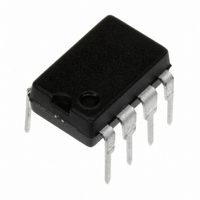
LM2578AN/NOPB National Semiconductor, LM2578AN/NOPB Datasheet - Page 9

LM2578AN/NOPB
Manufacturer Part Number
LM2578AN/NOPB
Description
IC REG SIMPLE SWITCHER 8-DIP
Manufacturer
National Semiconductor
Type
Step-Down (Buck), Step-Up (Boost), Inverting, Flybackr
Datasheet
1.LM3578AMNOPB.pdf
(20 pages)
Specifications of LM2578AN/NOPB
Internal Switch(s)
Yes
Synchronous Rectifier
No
Number Of Outputs
1
Current - Output
750mA
Frequency - Switching
20kHz
Voltage - Input
2 ~ 40 V
Operating Temperature
-40°C ~ 85°C
Mounting Type
Through Hole
Package / Case
8-DIP (0.300", 7.62mm)
No. Of Outputs
1
Output Voltage
1V
Output Current
750mA
No. Of Pins
8
Operating Temperature Range
-40°C To +85°C
Msl
MSL 1 - Unlimited
Input Voltage
40V
Input Voltage Primary Max
40V
Rohs Compliant
Yes
Primary Input Voltage
40V
Lead Free Status / RoHS Status
Lead free / RoHS Compliant
Voltage - Output
-
Power - Output
-
Other names
*LM2578AN
*LM2578AN/NOPB
LM2578AN
*LM2578AN/NOPB
LM2578AN
Applications Information
C.L. SENSE VOLTAGE MULTIPLICATION
When a larger sense resistor value is desired, the voltage
divider network, consisting of R1 and R2, may be used. This
effectively multiplies the sense voltage by (1 + R1/R2). Also,
R1 can be replaced by a diode to increase current limit
sense voltage to about 800 mV (diode V
FIGURE 6. Current Limit Sense Voltage Multiplication,
FIGURE 4. Current Limit Transient Suppressor,
FIGURE 5. Current Limit Transient Suppressor,
Ground Referred
Ground Referred
V
in
Referred
f
+ 110 mV).
(Continued)
00871117
00871119
00871118
9
UNDER-VOLTAGE LOCKOUT
Under-voltage lockout is accomplished with few external
components. When V
breakdown voltage, the output transistor is turned off. This
occurs because diode D1 will then become forward biased,
allowing resistor R3 to sink a greater current from the non-
inverting input than is sunk by the parallel combination of R1
and R2 at the inverting terminal. R3 should be one-fifth of the
value of R1 and R2 in parallel.
MAXIMUM DUTY CYCLE LIMITING
The maximum duty cycle can be externally limited by adjust-
ing the charge to discharge ratio of the oscillator capacitor
with a single external resistor. Typical values are 50 µA for
the charge current, 450 µA for the discharge current, and a
voltage swing from 200 mV to 750 mV. Therefore, R1 is
selected for the desired charging and discharging slopes
and C1 is readjusted to set the oscillator frequency.
FIGURE 7. Current Limit Sense Voltage Multiplication,
FIGURE 8. Under-Voltage Lockout
V
in
in
becomes lower than the zener
Referred
00871122
00871120
www.national.com


