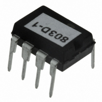
RF803D RF Solutions, RF803D Datasheet - Page 6

RF803D
Manufacturer Part Number
RF803D
Description
IC DECODER 3 DGTL I/O 8-PDIP
Manufacturer
RF Solutions
Type
Decoderr
Datasheet
1.RF803E-SO.pdf
(13 pages)
Specifications of RF803D
Applications
RF, IR
Mounting Type
Through Hole
Package / Case
8-DIP
Supply Voltage Range
2V To 5.5V
Digital Ic Case Style
DIP
No. Of Pins
8
Filter Terminals
DIP
Control Interface
Serial
Supply Voltage Max
5.5V
No. Of I/o's
3
Communication Function
Decoder
Rohs Compliant
Yes
Lead Free Status / RoHS Status
Lead free / RoHS Compliant
D
D
S
S
8
8
0
0
3
3
-
-
4
4
N
N
o
o
v
v
t
t
‘
‘
0
0
9
9
System and Functional operation
Pairing a Transmitter to a Receiver
Each transmitter has a unique identity. Each time a switch is pressed, the transmitter emits a highly
secure RF signal. The Receiver can learn this signal and allocate to an output.
Any transmitter switch may be paired to one or many of the receiver’s outputs, or a transmitter
single switch may be paired to any number of receiver’s outputs to enable a powerful and flexible
remote control system.
The only limitation is that each receiver has a maximum capacity of 15 pairings, these can be from
the same or any number of transmitters.
Hint: the same transmitter may be taught to any number of receivers to create ‘master keys’.
Learn Mode: Learn input activation is achieved by pulling this input to GND briefly
To learn a new transmitter switch follow this procedure (as application circuit)
Any Encoder input can be learnt to one or many of the receiver outputs.
Each input must be learnt to each output individually by following this procedure:
1. Select the receiver output to learn:
2. Operate whichever input on the encoder you want to learn to the selected decoder output.
3. The Learn LED will then illuminate, within 10secs, operate the same encoder input again.
4. The Learn LED will then flash to indicate learning is complete.
Erase Mode (As application circuit): is achieved by pulling this input to GND for >8 seconds. This
causes the internal EEPROM to be erased of all pre-learnt RF803E encoders.
During Erase the Learn LED will activate, it will extinguish when erase is complete.
Mom / Latch
This high impedance input is used to set the digital outputs to momentary or latched actions
Serial Data Output
The RF803D has a serial data output. This outputs the serial number, button and battery status of
the transmitter encoder (RF803E). This data may be fed directly to a microcontroller or RS232 type
driver circuit which may then be fed directly to a PC serial port.
Serial data is output initially and again every ½ second whilst data is being received from the
RF803E transmitter. i.e. this output is valid regardless of whether the RF803E encoder has been
learnt to the RF803D decoder or not. The serial data packet contains a learn bit to show if an
encoder input is learnt.
a. Briefly operate the receiver Learn switch (SW1) once
b. The Learn LED will flash once to indicate that output 1 is selected
c. After the LED stops flashing, press the Learn switch again to select the next output
d. Repeat step c until the required output is selected.
channel
E
E
n
n
©
©
LKIN Status
Open
Closed
2
2
0
c
0
c
0
0
8
8
T
T
o
o
R
R
e
e
l
l
F
F
d
0
0
d
S
S
1
1
2
2
o
o
e
e
7
7
l
l
u
u
3
3
t
t
i
i
r
r
o
8
o
8
n
n
9
9
s
8
s
8
/
/
0
0
L
L
0
0
t
t
d
d
0
0
D
D
,
,
F
F
w
w
a
a
w
w
e
e
x
x
w
w
0
0
.
.
c
1
1
c
r
r
f
f
2
2
s
s
7
7
o
o
o
o
3
3
l
l
u
u
4
4
t
t
d
i
i
d
8
8
o
o
0
n
0
n
6
s
6
s
e
e
.
.
6
6
Digital Outputs
Function
Latching
Momentary
c
c
1
1
o
o
r
r
.
.
u
u
k
k
I
I
C
C
’
’
s
s
P
P
a
a
g
g
e
e
6
6
R
R
F
F
8
8
0
0
3
3


