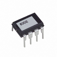
RF600E RF Solutions, RF600E Datasheet - Page 21

RF600E
Manufacturer Part Number
RF600E
Description
IC ENCODER TRANSMITTER RF 8DIP
Manufacturer
RF Solutions
Type
Encoderr
Datasheet
1.RF600E.pdf
(24 pages)
Specifications of RF600E
Applications
RF, IR
Mounting Type
Through Hole
Package / Case
8-DIP
Supply Voltage Range
2V To 6.6V
Operating Temperature Range
-55°C To +125°C
Digital Ic Case Style
DIP
No. Of Pins
8
Filter Terminals
SMD
Supply Voltage Max
6.6V
Supply Current
1.6mA
Ic Generic Number
60
Available stocks
Company
Part Number
Manufacturer
Quantity
Price
Company:
Part Number:
RF600E
Manufacturer:
RF Solutions
Quantity:
101
DS600-10 March ‘06
Input data mark.
The data stream received by the RF600D chip may be inverted as it passes through the radio or IR path.
When the bit stream is generated by the KeeLoq chip a 4 element sync pattern is inserted to allow the
RF600D chip to detect the end of the ‘01’ run-in part of the stream and the start of the data. At the output
terminal of the KeeLoq chip this 4 element sync pattern consists of 4 elements of data ‘0’ and if the radio
or IR data path does not invert the data then we would see this 4 element pattern in the data stream at the
input terminal of the RF600D chip. In this case we would say that the ‘mark’ of the incoming data is –ve
(low). If however the data path inverts the data stream then we would see 4 elements of data ‘1’ and we
would say that the data ‘mark’ is +ve (high).
In order for the RF600D chip to be able to decode the incoming bit stream it has to know the mark of the
incoming data and this is set on pin 8 of the device. This pin is normally used as an output to drive the
clock line of the EEPROM but when the EEPROM is not selected (CS is held low) then the state of this pin
is not recognised by the device. If we now change this pin on the RF600D to an input we can read the
logic level of the pin and use this to set the incoming data mark. The mark setting is done on option link
OPT3 according to the following table.
Learn and erase.
The learn switch serves to place the RF600D subsystem into either learn mode or erase mode. The learn
mode is used to initiate the process whereby the subsystem learns the KeeLoq parameters of a new
encoder device and places these into the EEPROM. The erase mode is used to wipe all encoder
parameters from the EEPROM.
To actuate the learn mode the LEARN-1 switch should be briefly operated at which point the adjacent LED
will light up. A button on the encoder to be learned should now be operated briefly, causing the LED on the
evaluation board to extinguish. Now re-operate the same button on the encoder and the LED on the
evaluation board will flash on and off for several seconds indicating that the learn process is complete. Up
to 50 encoders can be learned by one decoder and if additional attempts are made to learn new encoders
then each new learn process will overwrite the oldest learned data block.
Erasure of all learnt data can be carried out by pressing and holding down the LEARN-1 switch for at least
8 seconds. The LED will be on when the button is down and will then flash when the switch is released,
indicating that the EEPROM is being erased. When the LED is extinguished, all EEPROM data will have
been erased.
Serial data output
As mentioned above, the RF600D subsystem produces a serial data output which can be fed into another
microcontroller or RS232 driver. The configuration of this output is fully documented earlier in this
datasheet (SA123)
Digital Output Circuit.
The data outputs from the RF600D chip consist of the following signals:
The data outputs from the RF600D are connected to four LED’s such that switch inputs S0 – S3 on the
encoder have their state mirrored on LED’s LED2 – LED5. Thus when encoder input S0 is taken high,
LED 2 will come on and the others will remain off. Note that the data outputs are made available on J5.
The low battery output from the RF600D is connected to LED 6 such that if the encoder battery level falls
below 3.5 volts (typical) then the LED will come on. This indication is true only for the duration of the
transmission. Note that the low battery output is made available on J5.
1. Data outputs mirroring the 4 switch inputs on the RF600E chip.
2. The low battery flag from the RF600E chip.
RF / IR Encoder / Decoder Chipset
RF Evaluation Boards,
Data mark
+ve
-ve
data type
FM and IR
AM
©2004 Reg. No. 227 4001, ENGLAND
make link
+ve / FM
-ve / AM
Page 21
RF600E
RF600D


