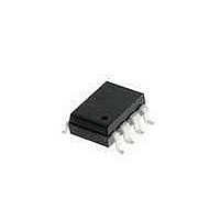
HCPL-4731#320 Avago Technologies US Inc., HCPL-4731#320 Datasheet - Page 11

HCPL-4731#320
Manufacturer Part Number
HCPL-4731#320
Description
OPTOCOUPLER 2CH HS UL 8-SMD GW
Manufacturer
Avago Technologies US Inc.
Datasheet
1.HCPL-073A-000E.pdf
(17 pages)
Specifications of HCPL-4731#320
Input Type
DC
Package / Case
8-SMD Gull Wing
Voltage - Isolation
5000Vrms
Number Of Channels
2, Unidirectional
Current - Output / Channel
60mA
Data Rate
100KBd
Propagation Delay High - Low @ If
65µs @ 40µA
Current - Dc Forward (if)
5mA
Output Type
Open Collector
Mounting Type
Surface Mount, Gull Wing
Isolation Voltage
3750 Vrms
Minimum Forward Diode Voltage
1.1 V
Output Device
Photodarlington
Configuration
2 Channel
Current Transfer Ratio
25000 %
Maximum Baud Rate
100 KBps
Maximum Forward Diode Voltage
1.4 V
Maximum Reverse Diode Voltage
2.5 V
Maximum Input Diode Current
10 mA
Maximum Power Dissipation
115 mW
Maximum Operating Temperature
+ 85 C
Minimum Operating Temperature
- 40 C
Lead Free Status / RoHS Status
Contains lead / RoHS non-compliant
Available stocks
Company
Part Number
Manufacturer
Quantity
Price
Package Characteristics
*All typical values at T
**The Input-Output Momentary Withstand Voltage is a dielectric voltage rating that should not be interpreted as an input-output
continuous voltage rating. For the continuous voltage rating refer to the IEC/EN/DIN EN 60747-5-2 Insulation Characteristics
Table (if applicable), your equipment level safety specification or Avago Application Note 1074 entitled “Optocoupler Input-Output
Endurance Voltage.”
11
Switching Specifications (AC)
Over Recommended Operating Conditions T
*All typical values at T
Parameter
Propagation
Delay Time
Propagation
Delay Time
to Logic High
Output
Common Mode |CM
Transient
Immunity at
Logic High
Output
Common Mode |CM
Transient
Immunity at
Logic Low
Output
to Logic Low
at Output
Input-Output Momentary
Withstand Voltage**
Resistance
(Input-Output)
Capacitance
(Input-Output)
Insulation Leakage
Current (Input-Input)
Resistance (Input-Input)
Capacitance
(Input-Input)
Parameter
Option 020
Symbol
A
t
t
= 25 C and V
A
PHL
PLH
= 25 C and V
H
L
|
|
070A/073A
4701/4731
Device
HCPL-
Symbol HCPL- Min. Typ.* Max. Units
CC
CC
V
R
C
R
C
= 5 V, unless otherwise noted.
I
ISO
I-I
I-O
I-O
I-I
I-I
= 5 V.
1,000 10,000
1,000 10,000
Min.
Device
4701
4731
4731
073A
4731
073A
A
= 0 C to 70 C, V
Typ.* Max. Units
2,000
65
70
34
3
3750
5000
500
500
130
25
30
60
90
0.005
0.03
0.25
10
10
0.6
12
11
CC
V/ s
V/ s
s
s
= 3 V to 18 V, unless otherwise specified.
I
V
T
I
V
T
I
V
T
I
|V
T
I
|V
V
F
F
F
F
F
A
A
A
A
CC
CC
CM
CC
V rms
CM
= 40 A, R
= 40 A, R
= 0 mA, R
= 0.5 mA, R
= 40 A, R
CM
= 25 C
= 25 C
= 25 C,
= 25 C
pF
pF
= 3.3 to 5 V
= 3.3 to 5 V
= 3.3 to 5 V, T
= 10 V
| = 10 V
| = 10 V
A
Test Conditions
Test Conditions
RH
t = 1 min.,
T
V
RH
f = 1 MHz
RH
V
f = 1 MHz
p-p
A
I-O
I-I
L
L
p-p
L
L
p-p
,
= 25 C
= 4.7 to 11 k ,
= 500 VDC
= 11 to 16 k ,
L
= 11 to 16 k ,
= 11 to 16 k ,
= 500 VDC
R
R
,
I
I
= 4.7 to 11 k ,
F
F
45%, t = 5 s,
50%,
45%
L
L
= 0.5 mA,
= 0.5 mA,
A
= 4.7 k
= 4.7 k
= 25 C
Fig. Note
Fig. Note
7, 9 9, 10
7, 9 9, 10
8
8
3, 4a
3, 4
6, 7
6, 7
3
3
5
5


