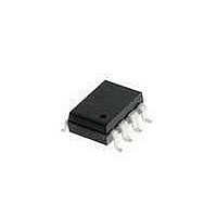
HCPL-4731#320 Avago Technologies US Inc., HCPL-4731#320 Datasheet - Page 13

HCPL-4731#320
Manufacturer Part Number
HCPL-4731#320
Description
OPTOCOUPLER 2CH HS UL 8-SMD GW
Manufacturer
Avago Technologies US Inc.
Datasheet
1.HCPL-073A-000E.pdf
(17 pages)
Specifications of HCPL-4731#320
Input Type
DC
Package / Case
8-SMD Gull Wing
Voltage - Isolation
5000Vrms
Number Of Channels
2, Unidirectional
Current - Output / Channel
60mA
Data Rate
100KBd
Propagation Delay High - Low @ If
65µs @ 40µA
Current - Dc Forward (if)
5mA
Output Type
Open Collector
Mounting Type
Surface Mount, Gull Wing
Isolation Voltage
3750 Vrms
Minimum Forward Diode Voltage
1.1 V
Output Device
Photodarlington
Configuration
2 Channel
Current Transfer Ratio
25000 %
Maximum Baud Rate
100 KBps
Maximum Forward Diode Voltage
1.4 V
Maximum Reverse Diode Voltage
2.5 V
Maximum Input Diode Current
10 mA
Maximum Power Dissipation
115 mW
Maximum Operating Temperature
+ 85 C
Minimum Operating Temperature
- 40 C
Lead Free Status / RoHS Status
Contains lead / RoHS non-compliant
Available stocks
Company
Part Number
Manufacturer
Quantity
Price
Figure 8. Test Circuit for Transient Immunity and Typical Waveforms.
V
Applications Information
Low-Power Operation
Current Gain
There are many applications
where low-power isolation is
needed and can be provided by
the single-channel HCPL-4701, or
the dual-channel HCPL-4731 low-
power optocouplers. Either or
both of these two devices are
referred to in this text as HCPL-
47XX product(s). These opto-
couplers are Avago’s lowest input
current, low-power optocouplers.
Low-power isolation can be
defined as less than a milliwatt of
input power needed to operate
the LED of an optocoupler
13
Figure 9. Switching Test Circuit.
CM
(SATURATED
RESPONSE)
0 V
V
V
10 V
O
O
SWITCH AT A: I = 0 mA
SWITCH AT B: I = 0.5 mA
t
PHL
V
I
F
O
0
t
r
10%
90%
F
F
1.5 V
90%
10%
t
f
1.5 V
5 V
V
OL
t
V
5 V
PLH
OL
(generally less than 500 A). This
level of input forward current
conducting through the LED can
control a worst-case total output
(I
(I
milliamperes. Typically, the
HCPL-47XX can control a total
output and supply current of 15
mA. The output current, I
determined by the LED forward
current multiplied by the current
gain of the optocoupler,
I
with the HCPL-47XX opto-
couplers, the LED can be driven
with a very small I
control a maximum I
O
ol
ccl
= I
) and power supply current
) of two and a half
10% DUTY CYCLE
I
F
F
MONITOR
1/f < 100 µs
(CTR)/100%. In particular
Z
V
t = 5 ns
O
PULSE
r
FF
GEN.
= 50
I
F
A
B
R
I
M
F
F
of 40 A to
O
1
2
3
4
of 320 A
1
2
3
4
* C
PROBE AND STRAY WIRING CAPACITANCE.
O
PULSE GEN.
L
IS APPROXIMATELY 15 pF, WHICH INCLUDES
+
is
V
CM
–
8
7
6
5
with a worst case design Current
Transfer Ratio (CTR) of 800%.
Typically, the CTR and the
corresponding I
larger. For low-power operation,
Table 1 lists the typical power
dissipations that occur for both
the 3.3 Vdc and 5 Vdc
HCPL-47XX optocoupler applica-
tions. These approximate power
dissipation values are listed
respectively for the LED, for the
output V
collector output transistor. Those
values are summed together for a
comparison of total power dissi-
pation consumed in either the 3.3
Vdc or 5 Vdc applications.
8
7
6
5
0.1 µF
R
220
CC
0.1 µF
CC
(SEE NOTE 7)
R
and for the open-
L
R
L
* C
+5 V
V
+5 V
V
L
ol
O
O
= 15 pF
, are 4 times


