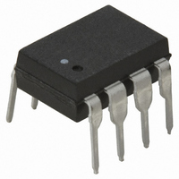
HCPL-4200 Avago Technologies US Inc., HCPL-4200 Datasheet - Page 10

HCPL-4200
Manufacturer Part Number
HCPL-4200
Description
OPTOCOUPLER RECEIVER 20MA 8-DIP
Manufacturer
Avago Technologies US Inc.
Type
Receiverr
Specifications of HCPL-4200
Mounting Type
Through Hole
Voltage - Isolation
3750Vrms
Input Type
DC
Voltage - Supply
4.5 V ~ 20 V
Operating Temperature
0°C ~ 70°C
Package / Case
8-DIP (0.300", 7.62mm)
No. Of Channels
1
Isolation Voltage
3.75kV
Optocoupler Output Type
Logic Gate
Input Current
24mA
Output Voltage
20V
Opto Case Style
DIP
No. Of Pins
8
Propagation Delay
0.23µs
Output Type
And
Package Type
8-Pin DIP
Lead Free Status / RoHS Status
Contains lead / RoHS non-compliant
Other names
516-1149-5
Available stocks
Company
Part Number
Manufacturer
Quantity
Price
Company:
Part Number:
HCPL-4200
Manufacturer:
AVAGO
Quantity:
5 000
Part Number:
HCPL-4200
Manufacturer:
AVAGO/安华高
Quantity:
20 000
Company:
Part Number:
HCPL-4200#300
Manufacturer:
AVAGO
Quantity:
7 000
Company:
Part Number:
HCPL-4200#500
Manufacturer:
AVAGO
Quantity:
7 000
Company:
Part Number:
HCPL-4200-000E
Manufacturer:
AVAGO
Quantity:
5 000
Part Number:
HCPL-4200-000E
Manufacturer:
AVAGO/安华高
Quantity:
20 000
Company:
Part Number:
HCPL-4200-300E
Manufacturer:
AVAGO
Quantity:
5 000
Part Number:
HCPL-4200-300E
Manufacturer:
AVAGO/安华高
Quantity:
20 000
Part Number:
HCPL-4200-500E
Manufacturer:
AVAGO/安华高
Quantity:
20 000
Figure 17. Simplex Current Loop System Configurations for (a) Point-to-Point, (b) Multidrop.
and OFF states. This non-isolated
active transmitter provides a
nominal 20 mA loop current for
the listed values of V
R3 in Figure 18.
Length of current loop (one
direction) versus minimum
required DC supply voltage, V
of the circuit in Figure 18 is
graphically illustrated in Figure
19. Multidrop configurations will
require larger V
predicts in order to account for
additional station terminal
voltage drops.
Typical data rate performance
versus distance is illustrated in
Figure 20 for the combination of
a non-isolated active transmitter
CC
than Figure 19
CC
, R2 and
CC
,
and HCPL-4200 optically coupled
current loop receiver shown in
Figure 18. Curves are shown for
10% and 25% distortion data
rate. 10% (25%) distortion data
rate is defined as that rate at
which 10% (25%) distortion
occurs to output bit interval with
respect to input bit interval. An
input Non-Return-to-Zero (NRZ)
test waveform of 16 bits
(0000001011111101) was used
for data rate distortion measure-
ments. Data rate is independent
of current source supply voltage,
V
The cable used contained five
pairs of unshielded, twisted, 22
AWG wire (Dearborn #862205).
Loop current is 20 mA nominal.
CC
.
10
Input and output logic supply
voltages are 5 V dc.
Full Duplex
The full duplex point-to-point
communication of Figure 21 uses
a four wire system to provide
simultaneous, bidirectional data
communication between local and
remote equipment. The basic
application uses two simplex
point-to-point loops which have
two separate, active, non-isolated
units at one common end of the
loops. The other end of each loop
is isolated.
As Figure 21 illustrates, the
combination of Agilent current
loop optocouplers, HCPL-4100
transmitter and HCPL-4200


