PVZ3G472C01R00 Murata Electronics North America, PVZ3G472C01R00 Datasheet - Page 4
PVZ3G472C01R00
Manufacturer Part Number
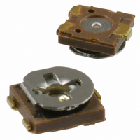
PVZ3G472C01R00
Description
POT 4.7K OHM 3MM TRIM 1TRN SMD
Manufacturer
Murata Electronics North America
Series
PVZ3r
Specifications of PVZ3G472C01R00
Resistance (ohms)
4.7K
Power (watts)
0.1W, 1/10W
Taper
Linear
Tolerance
±30%
Temperature Coefficient
±500ppm/°C
Number Of Turns
Single
Adjustment Type
Top Adjustment
Mounting Type
Surface Mount
Resistive Material
Carbon
Package / Case
Square - 0.122" L x 0.122" W x 0.045" H (3.10mm x 3.10mm x 1.15mm)
Resistance In Ohms
4.70K
Lead Free Status / RoHS Status
Lead free / RoHS Compliant
Other names
490-4628-2
Available stocks
Company
Part Number
Manufacturer
Quantity
Price
Company:

Part Number:
PVZ3G472C01R00
Manufacturer:
MURATA
Quantity:
240 000
Part Number:
PVZ3G472C01R00
Manufacturer:
MURATA/村田
Quantity:
20 000


5. Test Method
5.1 Contact resistance variation (CRV)
5.2 Temperature coefficient of resistance
5.3 Permitted force of Driver plate
5.4 Soldering strength
Contact resistance variation should be measured with the measuring circuit shown below, or its equivalent.
The operating wiper should be rotated in both directions through 90% of the actual effective electrical travel
for a total of 6 cycles. The rate of rotation of the operating wiper should be such that the wiper completes
1 count in determining whether or not a contact resistance variation is observed at least twice in the same
location.
The trimmer potentiometer should be subjected to
each of the following temperatures (see Table 1)
for 30 to 45 minutes. The resistance value
should be measured in the chamber.
A static load of 4.9N
second. The load should be applied on driver plate uniformly by the 3mm-size plate of push-pull gage.
The trimmer potentiometer should be soldered under the soldering condition described in paragraph 7.2(1) on
standard land pattern described in 9. Outline dimensions. A static load of 9.8N
from rear side through the hole opened in the center of PCB by the 1.0±0.1mm dia. stick for 5 second.
The tests and measurements should be conducted under the condition of 15 to 35°C of temperature,
25 to 75% of relative humidity and 86 to 106 kpa of atmospheric pressure unless otherwise specified.
If questionable results occur that have been measured in accordance with the above mentioned
conditions, the tests and measurements should be conducted under the condition of 25±2°C of
temperature and, 45 to 55% of relative humidity and 86 to 106 kpa of atmospheric pressure.
When the trimmer potentiometer is tested after soldering on PCB, it should be tested after being kept
in a room (15 to 35°C, 25 to 75%RH) over 24 hours except ” 5.12 Resistance to soldering heat“.
TC =
[Measurement circuit]
[Measurement wave]
CRV =
(Test current shown in below)
R
R
Constant Current Source
1
2
(T
2
- R
- T
IS • RX
1
1
(Ref; 500gf)
)
VN
X 10
VN
6
should be applied on the driver plate of the trimmer potentiometer for 5+1/-0
(ppm/°C)
Except ineffective
variable portion
#1
UNCONTROLLED
100(%)
REFERENCE ONLY
Proofread
Resistance
#2
Rx
COPY
RX:Trimmer Potentiometer
#3
[Test current for CRV]
IS : Test current for CRV
RX: Nominal total resistance of trimmer potentiometer
VN: Noise voltage (peak to peak)
Note)*: Norm Temp.
T
T
R
R
Temp. (°C)
Sequence
1
2
1
2
: Reference temperature in degrees Celsius
: Test temperature in degrees Celsius
: Resistance at reference temperature in ohm
: Resistance at test temperature in ohm
100k ohm<=R
Nominal total resistance
220 ohm<=R< 10k ohm
10k ohm<=R<100k ohm
+25±2
AC
Amplifier
*1
SPECIFICATION No. JVR03Z-7148B
Table 1
-25±3
2
Oscilloscope
(Ref; 1kgf)
+25±2
*3
should be applied
100µA max.
Test current
10mA max.
1mA max.
+85±3
4
4/12
Related parts for PVZ3G472C01R00
Image
Part Number
Description
Manufacturer
Datasheet
Request
R

Part Number:
Description:
BUZZER PIEZO 25VP-P SMD
Manufacturer:
Murata Electronics North America

Part Number:
Description:
CAP 4-ARRAY 680PF 100V X7R 1206
Manufacturer:
Murata Electronics North America
Datasheet:
Part Number:
Description:
CAP 4-ARRAY 1000PF 100V X7R 1206
Manufacturer:
Murata Electronics North America
Datasheet:
Part Number:
Description:
CAP 4-ARRAY 1800PF 100V X7R 1206
Manufacturer:
Murata Electronics North America
Datasheet:
Part Number:
Description:
CAP 4-ARRAY 68000PF 16V X7R 1206
Manufacturer:
Murata Electronics North America
Datasheet:

Part Number:
Description:
CAP CER 1000PF 50V 10% X7R 0402
Manufacturer:
Murata Electronics North America
Datasheet:
Part Number:
Description:
CAP CER 10000PF 16V 10% X7R 0402
Manufacturer:
Murata Electronics North America
Datasheet:

Part Number:
Description:
CAP 5.5-25PF 2.5X3.2MM SMD
Manufacturer:
Murata Electronics North America
Datasheet:

Part Number:
Description:
CAP 4.5-20PF 2.5X3.2MM SMD
Manufacturer:
Murata Electronics North America
Datasheet:

Part Number:
Description:
CAP 5.0-20PF 3.2X4.5MM SMD RED
Manufacturer:
Murata Electronics North America
Datasheet:

Part Number:
Description:
CAP 2.0-6.0PF 3.2X4.5MM SMD BLU
Manufacturer:
Murata Electronics North America
Datasheet:

Part Number:
Description:
CAP 1.4-3.0PF 3.2X4.5MM SMD BRN
Manufacturer:
Murata Electronics North America
Datasheet:

Part Number:
Description:
CAP 3.0-10PF 3.2X4.5MM SMD WHT
Manufacturer:
Murata Electronics North America
Datasheet:

Part Number:
Description:
CAP 2.0-6.0PF 4X4.5MM TOPADJ BLU
Manufacturer:
Murata Electronics North America
Datasheet:

Part Number:
Description:
CAP 8.5-40PF 4X4.5MM TOPADJ YEL
Manufacturer:
Murata Electronics North America
Datasheet: