LK5660-7R POWER ONE, LK5660-7R Datasheet - Page 21
LK5660-7R
Manufacturer Part Number
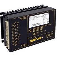
LK5660-7R
Description
CONVERTER AC/DC 225VIN 48VOUT
Manufacturer
POWER ONE
Series
Kr
Datasheet
1.LK5660-7R.pdf
(29 pages)
Specifications of LK5660-7R
Voltage - Output
24V
Number Of Outputs
2
Power (watts)
150W
Applications
Commercial
Power Supply Type
Switching (Closed Frame)
Voltage - Input
85 ~ 255VAC
Mounting Type
Chassis Mount
1st Output
24 VDC @ 3A
2nd Output
24 VDC @ 3A
Size / Dimension
6.63" L x 4.37" W x 3.15" H (168.5mm x 111mm x 80mm)
Power (watts) - Rated
150W
Operating Temperature
-25°C ~ 71°C
Efficiency
83%
Approvals
CE, cUL, EN, TUV
Output Voltage (channel 1)
24 V
Output Current (channel 1)
3 A
Output Voltage (channel 2)
24 V
Output Current (channel 2)
3 A
Isolation Voltage
2.8 KV
Output Type
Isolated
Lead Free Status / RoHS Status
Contains lead / RoHS non-compliant
3rd Output
-
4th Output
-
Lead Free Status / Rohs Status
Lead free / RoHS Compliant
Other names
LK 5660-7R
LK 5660-7R
Q1660869
LK 5660-7R
Q1660869


An additional external fuse, suitable for the application,
might be necessary in the wiring to the other line input 26 /
28 (N ~ ) if:
Make sure that there is sufficient airflow available for
convection cooling. This should be verified by measuring
the case temperature, when the converter is installed and
operated in the end-use application; see Thermal
Considerations.
Ensure that a converter failure (e.g., an internal short-
circuit) does not result in a hazardous condition; see also
Safety of Operator-Accessible Output Circuits.
Standards and Approvals
The converters are safety-approved to EN/IEC
60950-1, and UL/CSA 60950-1 2
106 or greater).
The converters correspond to Class I equip-
ment and have been evaluated for:
BCD20001-G Rev AC, 16-Dec-2010
• Local requirements demand an individual fuse in each
• Phase and neutral of the mains are not defined or
• Neutral and earth impedance is high or undefined
• Building-in
• Basic insulation between input and case based on 250
• Functional insulation between outputs.
Table 17: Isolation
Notes:
– If the inhibit function is not used, pin no. 18 (i) should be
– Do not open the converters, or warranty will be invalidated.
– Due to high current values, the converters provide two
– If the second output of double-output models is not used,
Characteristic
Electric
strength
test
Insulation resistance at 500 VDC
Creapage distances
1
2
3
source line
cannot be assigned to the corresponding terminals (L ~
to phase and N ~ to neutral).
VAC, and double or reinforced insulation between input
and output(s).
connected to pin no. 14 (S–/Vo1–) to enable the output(s).
internally parallel contacts for certain paths (pins 4/6, 8/10,
26/28 and 30/32). It is recommended to use both female
contacts in parallel connection order to keep the voltage
drop and the temperature of the contacts low.
connect it in parallel with the main output.
According to EN 50116 and IEC/EN 60950, subassemblies connecting input to output are pre-tested with 5.6 kVDC or 4 kVAC.
Tested at 150 VDC
Input to outputs: 6.4 mm
Factory test >1 s
AC test voltage equivalent
to factory test
nd
Ed. (version
and output(s)
Input to case
>300
2.8
2.0
3.2
Characteristic
Maximum earth
leakage current
1
3
Page 21 of 29
Table 16: Leakage currents
All boards of the converters are coated with a protective
lacquer.
The converters are subject to manufacturing surveillance
in accordance with the above mentioned UL standards
and ISO 9001:2000. A CB-scheme is available.
Cleaning Agents
In order to avoid possible damage, any penetration of
cleaning fluids is to be prevented, since the power
supplies are not hermetically sealed.
Protection Degree
Condition: Female connector fitted to the converter.
Leakage Currents
Leakage currents flow due to internal leakage capacitances
and Y-capacitors. The current values are proportional to the
supply voltage and are specified in the table below.
Isolation
The electric strength test is performed in the factory as
routine test in accordance with EN 50116 and IEC/EN
60950 and should not be repeated in the field. Power-One
will not honor any warranty claims resulting from electric
strength field tests.
• Overvoltage category II
• Pollution degree 2 environment
• Max. altitude: 2000 m.
• The converters fulfill the requirements of a fire enclosure.
• IP 30: All models except those with option P, and except
• IP 20: All models fitted with option P, or with option D or
those with option D or V including a potentiometer.
V with potentiometer.
Output(s) to
Permissible according to IEC/EN 60950
Typ. value at 254 V, 50 Hz (LK models)
Typ. value at 254 V, 50 Hz (LKP models)
case
>300
150 – 280 Watt AC-DC Converters
1.4
1.0
--
K Series with PFC Data Sheet
Output 1 to
output 2
>100
0.15
0.1
--
2
www.power-one.com
Class I
3.5
0.8
0.8
kVDC
kVAC
Unit
M
mm
Unit
mA
Related parts for LK5660-7R
Image
Part Number
Description
Manufacturer
Datasheet
Request
R

Part Number:
Description:
SWITCHING POWER SUPPLIES, SINGLE OUTPUT, 80 WATTS
Manufacturer:
POWER ONE
Datasheet:
Part Number:
Description:
HAS SERIES - 30 WATT
Manufacturer:
POWER ONE
Datasheet:
Part Number:
Description:
SINGLE OUTPUT
Manufacturer:
POWER ONE
Datasheet:

Part Number:
Description:
BRS DC/DC converters(1.5 WATT)
Manufacturer:
Power-One
Datasheet:
Part Number:
Description:
3...15 Watt DC-DC Converter
Manufacturer:
Power-One
Datasheet:
Part Number:
Description:
HBS SERIES - 100 WATT
Manufacturer:
Power-One
Datasheet:
Part Number:
Description:
3...15 Watt DC-DC Converter
Manufacturer:
Power-One
Datasheet:
Part Number:
Description:
BUS DC/DC converters(3 WATT)
Manufacturer:
Power-One
Datasheet:
Part Number:
Description:
HES SERIES 150 WATT
Manufacturer:
Power-One
Datasheet:
Part Number:
Description:
1.25 WATT
Manufacturer:
Power-One
Datasheet: