ADZS-21262-1-EZEXT Analog Devices Inc, ADZS-21262-1-EZEXT Datasheet - Page 8
ADZS-21262-1-EZEXT
Manufacturer Part Number
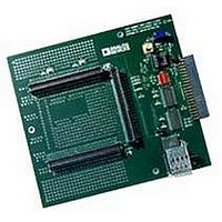
ADZS-21262-1-EZEXT
Description
BOARD DAUGHTER FOR ADSP-21262
Manufacturer
Analog Devices Inc
Datasheet
1.ADSP-21363KSWZ-1AA.pdf
(56 pages)
Specifications of ADZS-21262-1-EZEXT
Accessory Type
DSP
Silicon Manufacturer
Analog Devices
Core Architecture
SHARC
Features
Expansion Interface, High Speed Converter (HSC) Interface
Kit Contents
Board Docs
Silicon Family Name
SHARC
Silicon Core Number
ADSP-21262
Rohs Compliant
Yes
Lead Free Status / RoHS Status
Lead free / RoHS Compliant
For Use With/related Products
ADSP-21262
Lead Free Status / RoHS Status
Lead free / RoHS Compliant, Lead free / RoHS Compliant


ADSP-21362/ADSP-21363/ADSP-21364/ADSP-21365/ADSP-21366
audio channels in I2S, left-justified sample pair, or right-justi-
fied mode. One frame sync cycle indicates one 64-bit left/right
pair, but data is sent to the FIFO as 32-bit words (that is, one-
half of a frame at a time). The processor supports 24- and 32-bit
I
right-justified formats.
Precision Clock Generator (PCG)
The precision clock generators (PCG) consist of two units, each
of which generates a pair of signals (clock and frame sync)
derived from a clock input signal. The units, A and B, are identi-
cal in functionality and operate independently of each other.
The two signals generated by each unit are normally used as a
serial bit clock/frame sync pair.
Peripheral Timers
The following three general-purpose timers can generate peri-
odic interrupts and be independently set to operate in one of
three modes:
Each general-purpose timer has one bidirectional pin and four
registers that implement its mode of operation: a 6-bit configu-
ration register, a 32-bit count register, a 32-bit period register,
and a 32-bit pulse width register. A single control and status
register enables or disables all three general-purpose timers
independently.
I/O PROCESSOR FEATURES
The processor’s I/O provides many channels of DMA and con-
trols the extensive set of peripherals described in the previous
sections.
DMA Controller
The processor’s on-chip DMA controllers allow data transfers
without processor intervention. The DMA controller operates
independently and invisibly to the processor core, allowing
DMA operations to occur while the core is simultaneously exe-
cuting its program instructions. DMA transfers can occur
between the processor’s internal memory and its serial ports, the
SPI-compatible (serial peripheral interface) ports, the IDP
(input data port), the parallel data acquisition port (PDAP), or
the parallel port (PP). See
Table 4. DMA Channels
Peripheral
SPORTs
IDP/PDAP
SPI
MTM/DTCP
Parallel Port
Total DMA Channels
2
S, 24- and 32-bit left-justified, and 24-, 20-, 18- and 16-bit
• Pulse waveform generation mode
• Pulse width count/capture mode
• External event watchdog mode
Table
4.
ADSP-2136x
12
8
2
2
1
25
Rev. G | Page 8 of 56 | March 2011
SYSTEM DESIGN
The following sections provide an introduction to system design
options and power supply issues.
Program Booting
The internal memory of the processor boots at system power-up
from an 8-bit EPROM via the parallel port, an SPI master, an
SPI slave, or an internal boot. Booting is determined by the boot
configuration (BOOT_CFG1–0) pins in
boot source is controlled via the SPI as either a master or slave
device, or it can immediately begin executing from ROM.
Table 5. Boot Mode Selection
Phase-Locked Loop
The processors use an on-chip phase-locked loop (PLL) to gen-
erate the internal clock for the core. On power-up, the
CLK_CFG1–0 pins are used to select ratios of 32:1, 16:1, and
6:1. After booting, numerous other ratios can be selected via
software control.
The ratios are made up of software configurable numerator val-
ues from 1 to 64 and software configurable divisor values of 1, 2,
4, and 8.
Power Supplies
The processor has a separate power supply connection for the
internal (V
power supplies. The internal and analog supplies must meet the
1.2 V requirement for K, B, and Y grade models, and the 1.0 V
requirement for Y models. (For information on the temperature
ranges offered for this product, see
Page
on Page
ment. All external supply pins must be connected to the same
power supply.
Note that the analog supply pin (A
internal clock generator PLL. To produce a stable clock, it is rec-
ommended that PCB designs use an external filter circuit for the
A
A
recommended ferrite chip is the muRata BLM18AG102SN1D.)
To reduce noise coupling, the PCB should use a parallel pair of
power and ground planes for V
to connect the bypass capacitors to the analog power (A
and ground (A
specified in
log ground plane on the board—the A
directly to digital ground (GND) at the chip.
BOOT_CFG1–0
00
01
10
11
VDD
VDD
14,
/A
pin. Place the filter components as close as possible to the
VSS
54.) The external supply must meet the 3.3 V require-
Package Information on Page
DDINT
Figure 3
pins. For an example circuit, see
VSS
), external (V
) pins. Note that the A
are inputs to the processor and not the ana-
Booting Mode
SPI Slave Boot
SPI Master Boot
Parallel Port Boot via EPROM
No booting occurs. Processor executes
from internal ROM after reset.
DDEXT
DDINT
VDD
Operating Conditions on
), and analog (A
and GND. Use wide traces
VSS
) powers the processor’s
15, and
Table
VDD
pin should connect
Figure
and A
5. Selection of the
Ordering Guide
VSS
3. (A
VDD
pins
VDD
/A
VSS
)
)
Related parts for ADZS-21262-1-EZEXT
Image
Part Number
Description
Manufacturer
Datasheet
Request
R

Part Number:
Description:
BOARD DAUGHTER EZ EXTENDER
Manufacturer:
Analog Devices Inc
Datasheet:

Part Number:
Description:
±1.7g Dual-Axis IMEMS Accelerometer Evaluation Board
Manufacturer:
Analog Devices Inc
Datasheet:

Part Number:
Description:
Inertial Sensor Evaluation System
Manufacturer:
Analog Devices Inc
Datasheet:
Part Number:
Description:
Manufacturer:
Analog Devices Inc
Datasheet:
Part Number:
Description:
Manufacturer:
Analog Devices Inc
Datasheet:
Part Number:
Description:
Manufacturer:
Analog Devices Inc
Datasheet:
Part Number:
Description:
Manufacturer:
Analog Devices Inc
Datasheet:
Part Number:
Description:
Manufacturer:
Analog Devices Inc
Datasheet:
Part Number:
Description:
Manufacturer:
Analog Devices Inc
Datasheet:
Part Number:
Description:
Manufacturer:
Analog Devices Inc
Datasheet:
Part Number:
Description:
Manufacturer:
Analog Devices Inc
Datasheet:
Part Number:
Description:
Manufacturer:
Analog Devices Inc
Datasheet:
Part Number:
Description:
Manufacturer:
Analog Devices Inc
Datasheet: