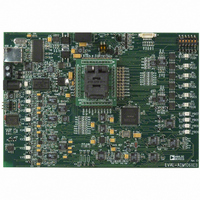
EVAL-ADM1062LFEB Analog Devices Inc, EVAL-ADM1062LFEB Datasheet - Page 27

EVAL-ADM1062LFEB
Manufacturer Part Number
EVAL-ADM1062LFEB
Description
BOARD EVALUATION FOR ADM1062LF
Manufacturer
Analog Devices Inc
Specifications of EVAL-ADM1062LFEB
Main Purpose
Power Management, Power Supply Supervisor/Tracker/Sequencer
Embedded
No
Utilized Ic / Part
ADM1062
Primary Attributes
10 Inputs, 10 Outputs (6 can be FET Drivers)
Secondary Attributes
Graphic User Interface
Lead Free Status / RoHS Status
Contains lead / RoHS non-compliant
Preliminary Technical Data
Figure 48. SMBus Jump
PROGRAMMING THE TIMEOUT FUNCTION
Programming the Timeout event is the opposite of programming
the Sequence. It takes the format “ IF event has NOT occurred
AFTER Xms THEN GOTO StateX. The software automatically
generates most of the statement. The only programmable elements
are the length of the timeout and the State to exit to.
Figure 49. Programming the Timeout
The Timeout function can also be programmed independently of the
Sequence function. In this case there will be an unconditional
timeout before moving to the next state. The user can program this
simply to put an extended delay between one event and the next
occurring. The maximum timeout delay is 400ms, but if a delay
longer than this is required, the user can cascade a number of states
together, setting the Timeout in each state.
When SMBus Jump is
selected a symbol is
placed on the far left
of the ‘Sequencing
Engine Program’
Click to enable
Timeout
The sequence will enter the state where this command has
been selected and wait for an SMBus Jump command to
be issued by the user
The timeout statement
is the inverse of the
sequence statement
Pressing this button
will issue the
SMBus Jump
command
Rev. PrB | Page 27 of 38
Figure 50. Programming an unconditional Timeout
PROGRAMMING THE MONITOR FUNCTION
The Monitor function, as described above, is a wide OR gate
whose inputs are the status of all of the ADM106x’s inputs,
including the ADC inputs (these are OR’ed together prior to
this and output a single WARNING function). The user can
select which inputs are to be monitored in a given state, and the
polarity that input must assert before action is taken. The action
taken is to GOTO another state. Again, the user can select
which state to go to.
Note: The supply fault detectors assert a 1 when a fault is
detected. When programming the Monitor function the user
should select “IF <INPUT = 1>” if they want action to be
taken when a supply goes out of tolerance. The software will
indicate if the VXn is in digital or analog mode by displaying
Hi/Lo if the VXn input is set to a digital mode and OK/FLT if it
is set to analog mode.
The programming of the Monitor function is shown below.
Figure 51. Programming the Monitor Function
Programming the Monitor function can also be done
independently of the Sequence or Timeout function. For
instance, once a power up sequence is completed, the user may
Click to enable
monitor
Select Hi/Lo or OK/FLT using these
drop down boxes. N.B. Fault(FLT) = 1
EVAL-ADM106x
Unconditional timeout


