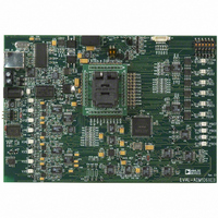
EVAL-ADM1062LFEB Analog Devices Inc, EVAL-ADM1062LFEB Datasheet - Page 28

EVAL-ADM1062LFEB
Manufacturer Part Number
EVAL-ADM1062LFEB
Description
BOARD EVALUATION FOR ADM1062LF
Manufacturer
Analog Devices Inc
Specifications of EVAL-ADM1062LFEB
Main Purpose
Power Management, Power Supply Supervisor/Tracker/Sequencer
Embedded
No
Utilized Ic / Part
ADM1062
Primary Attributes
10 Inputs, 10 Outputs (6 can be FET Drivers)
Secondary Attributes
Graphic User Interface
Lead Free Status / RoHS Status
Contains lead / RoHS non-compliant
EVAL-ADM106x
only be interested in taking action if a supply subsequently fails. In
this case, only the Monitor function needs to be programmed.
EXPANDING THE SEQUENCE SCREEN
In most applications the sequencing engine program will become
long and complex. To view the program in full screen click the
up/down arrow icon left of the ‘sequencing engine program’ title to
expand/shrink the program window. See figure 52.
Figure 52. Expaning Sequencing engine program
ENABLE ROUND ROBIN (ADM1062/3/4/6/9)
The ADM1062/3/4/6/9 have an on- board, 12 bit ADC. A 12
channel (13 on the ADM1063) mux enables the ADC to measure the
voltage on the input pins, the temperature sensors (ADM1062/3)
and the auxiliary pins (ADM1066). The user can choose which
inputs the ADC reads (see section on Read-back). Once selected,
the ADC cycles around each of the selected inputs in a “Round
Robin” fashion and does a conversion on each channel. The Round
Robin can be enabled in each individual state. This level of control
is provided since the user is unlikely to always want the ADC to be
converting. A typical example would be during a power up
sequence. As supplies are turning on, and have yet to reach their
nominal value, measuring the voltage as they ramp up is of little
meaning, since as this value is communicated across the SMBus to a
processor the voltage will already have increased to a different
value. Once the supplies have reached a quiescent condition, the
user may wish to monitor exactly what level the supplies are at.
Thus, the user could enable the Round Robin in the quiescent or
POWER GOOD state.
ENABLE FAULT LATCH
The ADM106x contains a fault plane (consisting of a number of
registers) which indicate the exact source of a fault once it occurs.
A bit each in these registers is assigned to the input channels of the
device. Enabling the fault latch ensures that the fault events are
latched on this fault plane, allowing the user to read the fault
registers in order to determine which input faulted. Again, the fault
Shrink/Expand
Sequencing
Engine Program
Rev. PrB | Page 28 of 38
latch can be enabled on an individual state basis. Typically the
fault latch is enabled in a powerloop state to capture faulting
supplies. It is not normally enabled during power up or power
down sequences where many supplies would be off and register
as under voltage (UV) faults. UV or over voltage (OV) faults
can also be distinguished.
SEQUENCING ENGINE PROGRAM EDITING
TOOLS
The ‘Sequencing Engine Program’ is a textual description of
what each state is programmed to. To edit a state, click on the
line in which this state appears. The contents of this state
program will appear in the ‘State Editor’.
Figure 53. Round Robin/Fault Latch Enable
Figure 54. Sequencing Engine Program
Enable Fault Latch and Round Robin
using these two check boxes
Preliminary Technical Data
Software reports when Round Robin
and Fault Latch have been selected.
State editing tools


