MCP2150DM Microchip Technology, MCP2150DM Datasheet - Page 10
MCP2150DM
Manufacturer Part Number
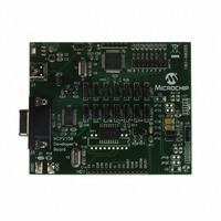
MCP2150DM
Description
BOARD DEMO FOR MCP2150
Manufacturer
Microchip Technology
Specifications of MCP2150DM
Main Purpose
Interface, IrDA
Embedded
Yes, MCU, 8-Bit
Utilized Ic / Part
MCP2150
Primary Attributes
IrDA Controller with PIC18F MCU
Secondary Attributes
USB Interface
Processor To Be Evaluated
MCP2150, MCP2155
Processor Series
MCP215x
Interface Type
USB
Lead Free Status / RoHS Status
Lead free / RoHS Compliant
Lead Free Status / RoHS Status
Lead free / RoHS Compliant, Lead free / RoHS Compliant


MCP2150
2.8
The device can be placed in a low power mode by dis-
abling the device (holding the EN pin at the low state).
The internal state machine is monitoring this pin for a
low level and, once this is detected, the device is
disabled and enters into a low power state.
2.8.1
When disabled, the device is in a low power state.
When the EN pin is brought to a high level, the device
will return to the operating mode. The device requires
a delay of 1024 T
or received.
FIGURE 2-5:
DS21655B-page 10
Minimizing Power
LLC (Logical Link Control)
Acceptance Filtering
Overload Notification
Recovery Management
MAC (Medium Access Control)
Data Encapsulation/Decapsulation
Frame Coding (stuffing, destuffing)
Medium Access Management
Error Detection
Error Signalling
Acknowledgment
Serialization/Deserialization
PLS (Physical Signalling)
Bit Encoding/Decoding
Bit Timing
Synchronization
PMA (Physical Medium Attachment)
Driver/Receiver Characteristics
MDI (Medium Dependent Interface)
Connectors
RETURNING TO DEVICE
OPERATION
OSI REFERENCE LAYERS
OSC
Data Link Layer
Physical Layer
before data may be transmitted
ISO REFERENCE LAYER MODEL
Presentation
Application
Transport
Network
Session
Preliminary
2.9
Figure 2-5
Model. The shaded areas are implemented by the
MCP2150, the cross-hatched area is implemented by
an infrared transceiver. The unshaded areas should be
implemented by the Host Controller.
Network Layering Reference
Model
shows the ISO Network Layering Reference
Has to be implemented in Host
Controller firmware
(such as a PICmicro
microcontroller)
Regions implemented
by the MCP2150
Regions implemented
by the Optical Transceiver logic
Fault
confinement
(MAC-LME)
Bus Failure
management
(PLS-LME)
Supervisor
2002 Microchip Technology Inc.
®
Related parts for MCP2150DM
Image
Part Number
Description
Manufacturer
Datasheet
Request
R

Part Number:
Description:
Manufacturer:
Microchip Technology Inc.
Datasheet:
Part Number:
Description:
Manufacturer:
Microchip Technology Inc.
Datasheet:
Part Number:
Description:
Manufacturer:
Microchip Technology Inc.
Datasheet:
Part Number:
Description:
Manufacturer:
Microchip Technology Inc.
Datasheet:
Part Number:
Description:
Manufacturer:
Microchip Technology Inc.
Datasheet:
Part Number:
Description:
Manufacturer:
Microchip Technology Inc.
Datasheet:
Part Number:
Description:
Manufacturer:
Microchip Technology Inc.
Datasheet:
Part Number:
Description:
Manufacturer:
Microchip Technology Inc.
Datasheet: