MCP2150DM Microchip Technology, MCP2150DM Datasheet - Page 9
MCP2150DM
Manufacturer Part Number
MCP2150DM
Description
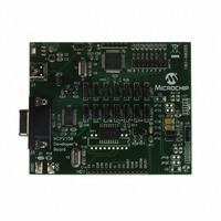
BOARD DEMO FOR MCP2150
Manufacturer
Microchip Technology
Specifications of MCP2150DM
Main Purpose
Interface, IrDA
Embedded
Yes, MCU, 8-Bit
Utilized Ic / Part
MCP2150
Primary Attributes
IrDA Controller with PIC18F MCU
Secondary Attributes
USB Interface
Processor To Be Evaluated
MCP2150, MCP2155
Processor Series
MCP215x
Interface Type
USB
Lead Free Status / RoHS Status
Lead free / RoHS Compliant
Lead Free Status / RoHS Status
Lead free / RoHS Compliant, Lead free / RoHS Compliant


2.6
The data that the MCP2150 UART received (on the TX
pin) that needs to be transmitted (on the TXIR pin) will
need to be modulated. This modulated signal drives the
IR transceiver module.
of the modulated signal.
Each bit time is comprised of 16-bit clocks. If the value
to be transmitted (as determined by the TX pin) is a
logic low, then the TXIR pin will output a low level for
7-bit clock cycles, a logic high level for 3-bit clock
cycles or a minimum of 1.6 µsec. (see
IR121). The remaining 6-bit clock cycles will be low. If
the value to transmit is a logic high, then the TXIR pin
will output a low level for the entire 16-bit clock cycles.
FIGURE 2-3:
FIGURE 2-4:
2002 Microchip Technology Inc.
Note:
BITCLK
(CLK)
BITCLK
RXIR Bit
Value
RX
TX Bit
Value
TXIR
Modulation
The signal on the TXIR pin does not actu-
ally line up in time with the bit value that
was transmitted on the TX pin, as shown in
Figure
represent the value to be transmitted on
the TXIR pin.
2-3. The TX bit value is shown to
Start Bit
16 CLK
16 CLK
Start Bit
16 CLK
ENCODING
DECODING
Figure 2-3
0
1.6 µs (up to 3 CLK)
0
7 CLK
24 Tosc
shows the encoding
Data bit 0
16 CLK
Data bit 0
13 CLK
1
1
parameter
Data bit 1
16 CLK
Data bit 1
Preliminary
0
0
Data bit 2
2.7
The modulated signal (data) from the IR transceiver
module (on RXIR pin) needs to be demodulated to form
the received data (on RX pin). Once demodulation of
the data byte occurs, the data that is received is trans-
mitted by the MCP2150 UART (on the RX pin).
Figure 2-4
signal.
Each bit time is comprised of 16-bit clocks. If the value
to be received is a logic low, then the RXIR pin will be
a low level for the first 3-bit clock cycles or a minimum
of 1.6 µs. The remaining 13-bit clock cycles (or differ-
ence up to the 16-bit clock time) will be high. If the value
to be received is a logic high, then the RXIR pin will be
a high level for the entire 16-bit clock cycles. The level
on the RX pin will be in the appropriate state for the
entire 16 clock cycles.
16 CLK
Data bit 2
Note:
0
0
Demodulation
The signal on the RX pin does not actually
line up in time with the bit value that was
received on the RXIR pin, as shown in
Figure
represent the value to be transmitted on
the RX pin.
shows the decoding of the modulated
Data bit ...
16 CLK
Data bit ...
2-4. The RXIR bit value is shown to
1
1
16 CLK
MCP2150
0
0
DS21655B-page 9
Related parts for MCP2150DM
Image
Part Number
Description
Manufacturer
Datasheet
Request
R

Part Number:
Description:
Manufacturer:
Microchip Technology Inc.
Datasheet:
Part Number:
Description:
Manufacturer:
Microchip Technology Inc.
Datasheet:
Part Number:
Description:
Manufacturer:
Microchip Technology Inc.
Datasheet:
Part Number:
Description:
Manufacturer:
Microchip Technology Inc.
Datasheet:
Part Number:
Description:
Manufacturer:
Microchip Technology Inc.
Datasheet:
Part Number:
Description:
Manufacturer:
Microchip Technology Inc.
Datasheet:
Part Number:
Description:
Manufacturer:
Microchip Technology Inc.
Datasheet:
Part Number:
Description:
Manufacturer:
Microchip Technology Inc.
Datasheet: