MCP2150DM Microchip Technology, MCP2150DM Datasheet - Page 5
MCP2150DM
Manufacturer Part Number
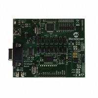
MCP2150DM
Description
BOARD DEMO FOR MCP2150
Manufacturer
Microchip Technology
Specifications of MCP2150DM
Main Purpose
Interface, IrDA
Embedded
Yes, MCU, 8-Bit
Utilized Ic / Part
MCP2150
Primary Attributes
IrDA Controller with PIC18F MCU
Secondary Attributes
USB Interface
Processor To Be Evaluated
MCP2150, MCP2155
Processor Series
MCP215x
Interface Type
USB
Lead Free Status / RoHS Status
Lead free / RoHS Compliant
Lead Free Status / RoHS Status
Lead free / RoHS Compliant, Lead free / RoHS Compliant


TABLE 1-2:
BAUD0
TXIR
RXIR
RESET
V
EN
TX
RX
RI
DSR
DTR
CTS
RTS
V
OSC2
OSC1/CLKIN
CD
BAUD1
Legend:
2002 Microchip Technology Inc.
Pin Name
SS
DD
TTL = TTL compatible input
I = Input
P = Power
PDIP SOIC SSOP
10
11
12
13
14
15
16
17
18
PIN DESCRIPTIONS
1
2
3
4
5
6
7
8
9
Pin Number
10
12
13
14
15
16
17
18
11
1
2
3
4
5
6
7
8
9
15, 16
5, 6
10
12
13
14
17
18
19
20
11
1
2
3
4
7
8
9
Type
Pin
—
—
—
O
O
O
O
O
O
I
I
I
I
I
I
I
I
I
ST = Schmitt Trigger input with CMOS levels
O = Output
CMOS = CMOS compatible input
CMOS Oscillator crystal input/external clock source input.
Buffer
Type
TTL
TTL
TTL
TTL
ST
ST
ST
ST
—
—
—
—
—
—
—
P
P
Preliminary
Resets the device.
Ground reference for logic and I/O pins.
Device enable.
1 = Device is enabled.
0 = Device is disabled (low power). MCP2150 only monitors
Asynchronous receive; from Host Controller UART.
Asynchronous transmit; to Host Controller UART.
Ring Indicator. The value on this pin is driven high.
Data Set Ready. Indicates that the MCP2150 has completed
reset.
1 = MCP2150 is initialized.
0 = MCP2150 is not initialized.
Data Terminal Ready. The value of this pin is ignored once
the MCP2150 is initialized. It is recommended that this pin be
connected so that the voltage level is either V
device power up, this signal is used with the RTS signal to
enter device ID programming.
1 = Enter Device ID programming mode (if RTS is cleared).
0 = Do not enter Device ID programming mode.
Clear to Send. Indicates that the MCP2150 is ready to
receive data from the Host Controller.
1 = Host Controller should not send data.
0 = Host Controller may send data.
Request to Send. Indicates that a Host Controller is ready to
receive data from the MCP2150. The MCP2150 prepares to
send data, if available.
1 = Host Controller not ready to receive data.
0 = Host Controller ready to receive data.
At device power up, this signal is used with the DTR signal to
enter device ID programming.
1 = Do not enter Device ID programming mode.
0 = Enter Device ID programming mode (if DTR is set).
Positive supply for logic and I/O pins.
Oscillator crystal output.
Carrier Detect. Indicates that the MCP2150 has established a
valid link with a Primary Device.
1 = An IR link has not been established (No IR Link).
0 = An IR link has been established (IR Link).
BAUD1:BAUD0 specify the baud rate of the device.
Asynchronous transmit to Infrared transceiver.
Asynchronous receive from Infrared transceiver.
BAUD1:BAUD0 specify the baud rate of the device.
this pin when in the NDM state.
Description
MCP2150
DS21655B-page 5
SS
or V
CC
. At
Related parts for MCP2150DM
Image
Part Number
Description
Manufacturer
Datasheet
Request
R

Part Number:
Description:
Manufacturer:
Microchip Technology Inc.
Datasheet:
Part Number:
Description:
Manufacturer:
Microchip Technology Inc.
Datasheet:
Part Number:
Description:
Manufacturer:
Microchip Technology Inc.
Datasheet:
Part Number:
Description:
Manufacturer:
Microchip Technology Inc.
Datasheet:
Part Number:
Description:
Manufacturer:
Microchip Technology Inc.
Datasheet:
Part Number:
Description:
Manufacturer:
Microchip Technology Inc.
Datasheet:
Part Number:
Description:
Manufacturer:
Microchip Technology Inc.
Datasheet:
Part Number:
Description:
Manufacturer:
Microchip Technology Inc.
Datasheet: