MCP2150DM Microchip Technology, MCP2150DM Datasheet - Page 15
MCP2150DM
Manufacturer Part Number
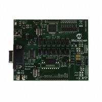
MCP2150DM
Description
BOARD DEMO FOR MCP2150
Manufacturer
Microchip Technology
Specifications of MCP2150DM
Main Purpose
Interface, IrDA
Embedded
Yes, MCU, 8-Bit
Utilized Ic / Part
MCP2150
Primary Attributes
IrDA Controller with PIC18F MCU
Secondary Attributes
USB Interface
Processor To Be Evaluated
MCP2150, MCP2155
Processor Series
MCP215x
Interface Type
USB
Lead Free Status / RoHS Status
Lead free / RoHS Compliant
Lead Free Status / RoHS Status
Lead free / RoHS Compliant, Lead free / RoHS Compliant


2.9.3
When two devices implementing the IrDA standard fea-
ture establish a connection using the IrCOMM protocol,
the process is analogous to connecting two devices
with serial ports using a cable. This is referred to as a
"point-to-point" connection. This connection is limited
to half-duplex operation because the IR transceiver
cannot transmit and receive at the same time. The pur-
pose of the IrDA protocol is to allow this half-duplex link
to emulate, as much as possible, a full-duplex connec-
tion. In general, this is done by dividing the data into
“packets”, or groups of data. These packets can then
be sent back and forth, when needed, without risk of
collision. The rules of how and when these packets are
sent constitute the IrDA protocols. The MCP2150 sup-
ports elements of this IrDA protocol to communicate
with other IrDA standard compatible devices.
When a wired connection is used, the assumption is
made that both sides have the same communications
parameters and features. A wired connection has no
need to identify the other connector because it is
assumed that the connectors are properly connected.
In the IrDA standard, a connection process has been
defined to identify other IrDA compatible devices and
establish a communication link. There are three steps
that these two devices go through to make this
connection. They are:
• Normal Disconnect Mode (NDM)
• Discovery Mode
• Normal Connect Mode (NCM)
Figure 2-10
2.9.3.1
When two IrDA standard compatible devices come into
range they must first recognize each other. The basis
of this process is that one device has some task to
accomplish and the other device has a resource
needed to accomplish this task. One device is referred
to as a Primary device and the other is referred to as a
Secondary device. This distinction between Primary
device and Secondary device is important. It is the
responsibility of the Primary device to provide the
mechanism to recognize other devices. So the Primary
device must first poll for nearby IrDA standard compat-
ible devices. During this polling, the defaut baud rate of
9600 baud is used by both devices.
For example, if you want to print from an IrDA
equipped laptop to an IrDA printer, utilizing the IrDA
standard feature, you would first bring your laptop in
range of the printer. In this case, the laptop is the one
that has something to do and the printer has the
resource to do it. The laptop is called the Primary
device and the printer is the Secondary device. Some
data-capable cellphones have IrDA standard infrared
ports. If you used such a cellphone with a Personal Dig-
2002 Microchip Technology Inc.
HOW DEVICES CONNECT
shows the connection sequence.
Normal Disconnect Mode (NDM)
Preliminary
ital Assistant (PDA), the PDA that supports the IrDA
standard feature would be the Primary device and the
cellphone would be the Secondary device.
When a Primary device polls for another device, a
nearby Secondary device may respond. When a Sec-
ondary device responds, the two devices are defined to
be in the Normal Disconnect Mode (NDM) state. NDM
is established by the Primary device broadcasting a
packet and waiting for a response. These broadcast
packets are numbered. Usually 6 or 8 packets are sent.
The first packet is number 0, the last packet is usually
number 5 or 7. Once all the packets are sent, the Pri-
mary device sends an ID packet, which is not num-
bered.
The Secondary device waits for these packets and then
responds to one of the packets. The packet it responds
to determines the “time slot” to be used by the Second-
ary device. For example, if the Secondary device
responds after packet number 2, then the Secondary
device will use time slot 2. If the Secondary device
responds after packet number 0, then the Secondary
device will use time slot 0. This mechanism allows the
Primary device to recognize as many nearby devices
as there are time slots. The Primary device will con-
tinue to generate time slots and the Secondary device
should continue to respond, even if there’s nothing to
do.
During NDM, the MCP2150 handles all of the
responses to the Primary device
any communication with the Host Controller. The Host
Controller is inhibited by the CTS signal of the
MCP2150 from sending data to the MCP2150.
Note 1: The MCP2150 can only be used to
2: The MCP2150 supports a system with
3: The MCP2150 always responds to packet
4: If another Secondary device is nearby,
implement a Secondary device.
only one Secondary device having exclu-
sive use of the IrDA standard infrared link
(known as "point-to-point" communica-
tion).
number 2. This means that the MCP2150
will always use time slot 2.
the Primary device may fail to recognize
the MCP2150, or the Primary device may
not recognize either of the devices.
MCP2150
(Figure
DS21655B-page 15
2-10) without
Related parts for MCP2150DM
Image
Part Number
Description
Manufacturer
Datasheet
Request
R

Part Number:
Description:
Manufacturer:
Microchip Technology Inc.
Datasheet:
Part Number:
Description:
Manufacturer:
Microchip Technology Inc.
Datasheet:
Part Number:
Description:
Manufacturer:
Microchip Technology Inc.
Datasheet:
Part Number:
Description:
Manufacturer:
Microchip Technology Inc.
Datasheet:
Part Number:
Description:
Manufacturer:
Microchip Technology Inc.
Datasheet:
Part Number:
Description:
Manufacturer:
Microchip Technology Inc.
Datasheet:
Part Number:
Description:
Manufacturer:
Microchip Technology Inc.
Datasheet:
Part Number:
Description:
Manufacturer:
Microchip Technology Inc.
Datasheet: