EVAL-AD9830EBZ Analog Devices Inc, EVAL-AD9830EBZ Datasheet
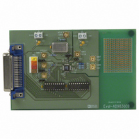
BOARD EVALUATION AD9830

EVAL-AD9830EBZ

Manufacturer Part Number
EVAL-AD9830EBZ
Description
BOARD EVALUATION AD9830
Manufacturer
Analog Devices Inc
Datasheets

Specifications of EVAL-AD9830EBZ

Main Purpose
Timing, Direct Digital Synthesis (DDS)
Utilized Ic / Part
AD9830
Lead Free Status / RoHS Status
Lead free / RoHS Compliant
Secondary Attributes
-
Embedded
-
Primary Attributes
-
Lead Free Status / Rohs Status
Supplier Unconfirmed
a
INTRODUCTION
This Application Note describes the evaluation board for the
AD9830 Direct Digital Synthesizer (DDS). The AD9830 is a
numerically controlled oscillator employing a phase
accumulator, a sine look-up table and a 10-bit D/A converter.
The part can be operated with clock frequencies up to 50
MHz. Both phase modulation and frequency modulation can
be performed with the AD9830. Full data on the AD9830 is
available in the AD9830 datasheet available from Analog
Devices and should be consulted in conjunction with this
Application Note when using the evaluation board.
The evaluation board interfaces to the parallel port of an IBM
compatible PC. Software is available with the evaluation
board which allows the user to easily program the AD9830.
Components on the AD9830 Evaluation Board include a 50
MHz oscillator which provides the MCLK for the AD9830.
The user can remove this oscillator, if required, and drive the
AD9830 with a different clock oscillator or an external clock
This Application Note applies to Version 2 of the AD9830 Evaluation Board
Information furnished by Analog Devices is believed to be accurate and
reliable. However, no responsibility is assumed by Analog Devices for
its use; nor for any infringements of patents or other rights of third parties
which may result from its use. No license is granted by implication or
otherwise under any patent or patent rights of Analog Devices.
FEATURES
Full-Featured Evaluation Board for the AD9830
Various Linking Options
PC Software for Control of AD9830
AD9830.EXE
IBM Compatible PC
Evaluation Board Setup
Evaluation Board for the AD9830
source via a BNC connector. Latches (74HC574) are also on
the board, these latches being used to hold the 16-bit data
word being written from the PC to the AD9830.
OPERATING THE AD9830 EVALUATION BOARD
Power Supplies
This evaluation board has two analog power supply inputs:
AVDD and AGND. AVDD equals +5 V and is used to
provide the AVDD for the AD9830. DGND and DVDD
connections are also available. The DVDD is used to provide
the DVDD for the AD9830, the 50 MHz oscillator and the
DVDD for the logic chips. DGND and AGND are
connected at the AD9830. Therefore, it is recommended not
to connect AGND and DGND elsewhere in the system.
All power supplies are decoupled to ground. AVDD and
DVDD are decoupled using 10 F tantalum capacitors and
0.1 F ceramic capacitors at the input to the evaluation board.
The power supplies are again decoupled using 0.1 F
capacitors at the AD9830, the crystal and the logic.
One Technology Way; P.O.BOX 9106; Norwood, MA 02062-9106 U.S.A.
Tel: 617/329-4700
Telex: 174059
Parallel Port Centronics
Printer Cable
Direct Digital Synthesizer
AD9830 Evaluation
EVAL-AD9830EB
Board
Cables: ANALOG NORWOOD MASS
Twx: 710/394-6577
REV 0

Related parts for EVAL-AD9830EBZ

EVAL-AD9830EBZ Summary of contents

Page 1

... The user can remove this oscillator, if required, and drive the AD9830 with a different clock oscillator or an external clock AD9830.EXE This Application Note applies to Version 2 of the AD9830 Evaluation Board Information furnished by Analog Devices is believed to be accurate and reliable. However, no responsibility is assumed by Analog Devices for its use ...

Page 2

... EVAL-AD9830EB Link and Switch Options There are five link options which must be set for the required operating setup before using the evaluation board. The functions of these options are outlined below. Link No. Function LK1 The PSEL1 input can be controlled by the user via a BNC connector or, alternatively, by switch SW. ...

Page 3

... Care should be taken before applying power and signals to the evaluation board to ensure that all link positions are as per the required operating mode. Table 1 shows the position in which all the links are set when the evaluation board is sent out. Table 1. Initial Link and Switch Positions Link No. ...

Page 4

... PCB Mounting Terminal Block. The Analog Power Supply to the Evaluation Board is provided via this Connector. SWITCHES There is one switch on the AD9830 evaluation board. This switch is a double throw, end stackable switch. This switch can be used to control the FSELECT, PSEL0 and PSEL1 inputs. ...

Page 5

... The executable program contains two menus. The first menu gives options on the type of PC being used. The printer port needs to be configured correctly for one of the three different PC-types for interfacing to the AD9830. Choose the required printer type from the menu. The PC printer port is now configured for operation with the AD9830 evaluation board. Running the AD9830 Software The second menu gives options for running the AD9830 ...

Page 6

... EVAL-AD9830EB SW or, alternatively, these inputs can be controlled using an external source via the BNC connectors. The AD9830 software also contains a demonstration procedure whereby the AD9830 can be made to step through a series of output frequencies. The user only has to load the start frequency, the stop frequency and the step size, and, the AD9830 software will program the AD9830 appropriately so that a frequency sweep will be performed at the AD9830 output ...

Page 7

... PSEL0 10 FSELECT MCLK 7 MCLK IOUT 3 SLEEP DVDD DGND AGND LK4 6, 13, 29 36, 39, 41, 46 XTAL1 COMPONENT LIST Links LK1 - LK4 LK5 Switch SW Sockets SMB1 - SMB7 Connectors J1 J2 AD7002 EVAL-AD9830EB C4, C5 AVDD SMB5 1 LK5 AVDD C7 DVDD 0 C10 1k R5 SMB6 45 51 SMB7 ...

Related keywords