EVALSF2-ICE2A0565Z-12 Infineon Technologies, EVALSF2-ICE2A0565Z-12 Datasheet - Page 13
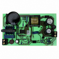
EVALSF2-ICE2A0565Z-12
Manufacturer Part Number
EVALSF2-ICE2A0565Z-12
Description
BOARD DEMO ICE2A0565Z 10W SMPS
Manufacturer
Infineon Technologies
Series
CoolSET®F2r
Specifications of EVALSF2-ICE2A0565Z-12
Main Purpose
AC/DC, Primary Side
Outputs And Type
1, Isolated
Power - Output
10W
Voltage - Output
5V
Current - Output
2A
Voltage - Input
85 ~ 270VAC
Regulator Topology
Flyback
Frequency - Switching
100kHz
Board Type
Fully Populated
Utilized Ic / Part
ICE2A0565
Lead Free Status / RoHS Status
Lead free / RoHS Compliant
Other names
EVALSF2-ICE2A0565Z-12IN


Figure 14
3.4
3.4.1
The oscillator generates a frequency f
100kHz. A resistor, a capacitor and a current source
and current sink which determine the frequency are
integrated. The charging and discharging current of the
implemented
trimmed, in order to achieve a very accurate switching
frequency. The ratio of controlled charge to discharge
current is adjusted to reach a max. duty cycle limitation
of D
3.4.2
The frequency of the oscillator is depending on the
voltage at pin FB. The dependence is shown in Figure
15. This feature allows a power supply to operate at
lower frequency at light loads thus lowering the
switching losses while maintaining good cross
regulation performance and low output ripple. In case
of low power the power consumption of the whole
SMPS can now be reduced very effective. The minimal
reachable frequency is limited to 20kHz/21.5 kHz to
avoid audible noise in any case.
Version 2.6
5.3V
4.8V
V
max
OUT
V
V
=0.72.
V
FB
SoftS
OUT
Oscillator and Frequency
Reduction
Oscillator
Frequency Reduction
Start Up Phase
T
oscillator
T
Start-Up
Soft-Start
capacitor
are
switch
= 67kHz/
internally
t
t
t
13
Figure 15
3.5
There is a cycle by cycle current limiting realized by the
Current-Limit Comparator to provide an overcurrent
detection. The source current of the integrated
CoolMOS
R
transformed to a sense voltage V
voltage V
V
off the gate drive. To prevent the Current Limiting from
distortions caused by leading edge spikes a Leading
Edge Blanking is integrated at the Current Sense.
Furthermore a Propagation Delay Compensation is
added to support the immediate shut down of the
CoolMOS™ in case of overcurrent.
3.5.1
Figure 16
Each time when CoolMOS™ is switched on a leading
spike
capacitances and secondary-side rectifier reverse
recovery time. To avoid a premature termination of the
switching pulse this spike is blanked out with a time
constant of t
csth
Sense
V
csth
V
the Current-Limit-Comparator immediately turns
kHz
21.5
. By means of R
100
Sense
65
is
1.0
f
f
standby
norm
Sense
TM
Current Limiting
Leading Edge Blanking
1.1
Frequency Dependence
Leading Edge Blanking
generated
LEB
is sensed via an external sense resistor
ICE2Axxxx
21.5kHz
100kHz
exceeds the internal threshold voltage
1.2
= 220ns. During that time the output of
1.3
ICE2Bxxxx
1.4
67kHz
20kHz
Functional Description
t
LEB
due
1.5
Sense
= 220ns
1.6
the source current is
to
1.7
CoolSET™-F2
V
1.8
the
FB
Sense
1.9
25 Dec 2006
. When the
primary-side
2.0
V
t
Related parts for EVALSF2-ICE2A0565Z-12
Image
Part Number
Description
Manufacturer
Datasheet
Request
R

Part Number:
Description:
Manufacturer:
Infineon Technologies AG
Datasheet:
Part Number:
Description:
Manufacturer:
Infineon Technologies AG
Datasheet:
Part Number:
Description:
Manufacturer:
Infineon Technologies AG
Datasheet:
Part Number:
Description:
Manufacturer:
Infineon Technologies AG
Datasheet:
Part Number:
Description:
Manufacturer:
Infineon Technologies AG
Datasheet:
Part Number:
Description:
Manufacturer:
Infineon Technologies AG
Datasheet:
Part Number:
Description:
Manufacturer:
Infineon Technologies AG
Datasheet:
Part Number:
Description:
16-bit microcontroller with 2x2 KByte RAM
Manufacturer:
Infineon Technologies AG
Datasheet:
Part Number:
Description:
NPN silicon RF transistor
Manufacturer:
Infineon Technologies AG
Datasheet:
Part Number:
Description:
NPN silicon RF transistor
Manufacturer:
Infineon Technologies AG
Datasheet:
Part Number:
Description:
NPN silicon RF transistor
Manufacturer:
Infineon Technologies AG
Datasheet:
Part Number:
Description:
NPN silicon RF transistor
Manufacturer:
Infineon Technologies AG
Datasheet:
Part Number:
Description:
Si-MMIC-amplifier in SIEGET 25-technologie
Manufacturer:
Infineon Technologies AG
Datasheet:
Part Number:
Description:
IGBT Power Module
Manufacturer:
Infineon Technologies AG
Datasheet:
Part Number:
Description:
IC for switching-mode power supplies
Manufacturer:
Infineon Technologies AG
Datasheet: