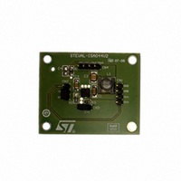
STEVAL-ISA044V2 STMicroelectronics, STEVAL-ISA044V2 Datasheet - Page 11

STEVAL-ISA044V2
Manufacturer Part Number
STEVAL-ISA044V2
Description
BOARD EVAL BASED ON ST1S10
Manufacturer
STMicroelectronics
Type
DC/DC Switching Converters, Regulators & Controllersr
Specifications of STEVAL-ISA044V2
Mfg Application Notes
ST1S10 AppNote
Main Purpose
DC/DC, Step Down
Outputs And Type
1, Non-Isolated
Current - Output
3A
Voltage - Input
2.5 ~ 18V
Regulator Topology
Buck
Frequency - Switching
900kHz
Board Type
Fully Populated
Utilized Ic / Part
ST1S10
Input Voltage
2.5 V to 18 V
Product
Power Management Modules
Silicon Manufacturer
ST Micro
Silicon Core Number
ST1S10
Kit Application Type
Power Management - Voltage Regulator
Rohs Compliant
Yes
Lead Free Status / RoHS Status
Lead free / RoHS Compliant
Voltage - Output
-
Power - Output
-
Lead Free Status / Rohs Status
Lead free / RoHS Compliant
For Use With/related Products
ST1S10
Other names
497-8229
STEVAL-ISA044V2
STEVAL-ISA044V2
ST1S10
5.6
5.7
5.8
5.8.1
Equation 8
T
where R
I
To ensure safe operating conditions the application should be designed to keep T
Inductor (V
The inductor value fixes the ripple current flowing through output capacitor and switching
peak current. The ripple current should be kept in the range of 20 - 40% of I
example it is 0.6 - 1.2 A at I
the following equation:
Equation 9
L = [(V
where T
T
The inductor should be selected with saturation current (I
inductor peak current, which can be calculated with the following equation:
Equation 10
I
The inductor peak current must be designed so that it does not exceed the switching current
limit.
Inductor (0.8 V < V
For applications with lower output voltage levels (V
previous section is still valid but it is recommended to keep the inductor values in a range
from 1 µH to 2.2 µH in order to improve the DC-DC control loop behavior, and increase the
output capacitance depending on the V
most application conditions a 2.2 µH inductor is the best compromise between DC-DC
control loop behavior and output voltage ripple.
Function operation
Sync operation
The ST1S10 operates at a fixed frequency or can be synchronized to an external frequency
with the SYNC pin. The ST1S10 switches at a frequency of 900 kHz when the SYNC pin is
connected to ground, and can synchronize the switching frequency between 400 kHz to 1.2
MHz from an external clock applied to the SYNC pin. When the SYNC feature is not used,
this pin must be connected to ground with a path as short as possible to avoid any possible
noise injected in the SYNC internal circuitry.
OUT
PK
ON
J
= {[V
= I
= D/F
current and T
O
IN
OUT
ON
+ (ΔI
thJA
- V
S
is the ON time of the internal switch, given by:
OUT
x I
is the junction-to-ambient thermal resistance, η is the efficiency at the rated
SW
OUT
) / ΔI
/2), I
OUT
AMB
x R
SW
SAT
thJA
> 2.5 V)
is the ambient temperature.
] x T
≥ I
x (1-η)] / η} +T
OUT
PK
OUT
ON
Doc ID 13844 Rev 4
= 3 A). The approximate inductor value can be obtained with
< 2.5 V)
IN
AMB
level as shown in the
OUT
< 2.5 V) the description in the
SAT
) equal to or higher than the
Figure 4
Application information
and
OUT_MAX
Figure
J
< 140°C.
5. In
(for
11/26


