CY3218-CAPEXP1 Cypress Semiconductor Corp, CY3218-CAPEXP1 Datasheet - Page 10
CY3218-CAPEXP1
Manufacturer Part Number
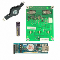
CY3218-CAPEXP1
Description
KIT CAPSENSE EXPRESS CY8C20110
Manufacturer
Cypress Semiconductor Corp
Series
CapSense Express™r
Specifications of CY3218-CAPEXP1
Sensor Type
Touch, Capacitive
Interface
I²C, USB
Voltage - Supply
0.9 V ~ 1.5 V
Embedded
Yes, Other
Utilized Ic / Part
CY8C20110
Processor To Be Evaluated
CY8C201x
Lead Free Status / RoHS Status
Lead free / RoHS Compliant
Sensitivity
-
Sensing Range
-
Lead Free Status / Rohs Status
Lead free / RoHS Compliant
Other names
428-2043
Available stocks
Company
Part Number
Manufacturer
Quantity
Price
Company:

Part Number:
CY3218-CAPEXP1
Manufacturer:
CYPRESS
Quantity:
15


Operating Modes of I
Normal Mode
In normal mode of operation, the acknowledgment time is
optimized. The timings remain approximately the same for
different configurations of the slave. To reduce the
acknowledgment times in normal mode, the registers
0x06–0x09, 0x0C, 0x0D, 0x10–0x17, 0x50, 0x51, 0x57–0x60,
0x7E are given only read access. Write to these registers can be
done only in setup mode.
Setup Mode
All registers have read and write access (except those which are
read only) in this mode. The acknowledgment times are longer
compared to normal mode. When CapSense scanning is
disabled (command code 0x0A in command register 0xA0), the
acknowledgment times can be improved to values similar to the
normal mode of operation.
Device Operation Modes
CapSense Express devices are configured to operate in any of
the following three modes to meet different power consumption
requirements:
■
■
■
Active Mode
In the active mode, all the device blocks including the CapSense
sub system are powered. Typical active current consumption of
the device across the operating voltage range is 1.5 mA.
Periodic Sleep Mode
Sleep mode provides an intermediate power operation mode. It
is enabled by configuring the corresponding device registers
(0x7E, 0x7F). The device goes into sleep after there is no event
for stay awake counter (Reg 0x80) number of sleep intervals.
The device wakes up on sleep interval and It scans the
capacitive sensors before going back to sleep again. If any
sensor is active, then the device wakes up. The device can also
wake up from sleep mode with a GPIO interrupt. The following
sleep intervals are supported in CapSense Express. The sleep
interval is configured through registers.
■
■
■
■
Document Number: 001-54606 Rev. *E
Active Mode
Periodic Sleep Mode
Deep Sleep Mode
1.95 ms (512 Hz)
15.6 ms (64 Hz)
125 ms (8 Hz)
1 s (1 Hz)
2
C Commands
Deep Sleep Mode
Deep sleep mode provides the lowest power consumption
because there is no operation running. All CapSense scanning
is disabled during this mode. In this mode, the device wakes up
only using an external GPIO interrupt. A sleep timer interrupt
cannot wake up a device from deep sleep mode. This is treated
as a continuous sleep mode without periodic wakeups. Refer to
the application note
Considerations” - AN44209
To get the lowest power during this mode the sleep timer
frequency should be set to 1 Hz.
Sleep Control Pin
The devices require a dedicated sleep control pin to enable
reliable I
This is achieved by pulling the sleep control pin low to wake up
the device and start I
can be configured on any GPIO.
Interrupt Pin to Master
To inform the master of any button press a GPIO can be
configured as interrupt output and all CapSense buttons can be
connected to this GPIO with an OR logic operator. This can be
configured using the software tool.
LED Dimming
To change the brightness and intensity of the LEDs, the host
master (MCU, MPU, DSP, and so on) must send I
and program the PWM registers to enable output pins, set duty
cycle, and mode configuration. The single PWM source is
connected to all GPIO pins and has a common user defined duty
cycle. Each PWM enabled pin has two possible outputs: PWM
and 0/1 (depending on the configuration). Four different modes
of LED dimming are possible, as shown in
1: Change Intensity on ON/OFF Button Status”
“LED Dimming Mode 4: Toggle Intensity on ON/OFF or OFF/ON
Button Transitions”
cycle of the PWM enabled pins is common. This means that one
pin cannot behave as in Mode 1 and another pin as in Mode 2.
2
C communication in case any sleep mode is enabled.
on page 12. The operation mode and duty
“CapSense Express Power and Sleep
2
C communication. The sleep control pin
CY8C20160, CY8C20140
CY8C20110, CY8C20180
for details on different sleep modes.
“LED Dimming Mode
CY8C20142
on page 11 to
2
Page 10 of 39
C commands
[+] Feedback
Related parts for CY3218-CAPEXP1
Image
Part Number
Description
Manufacturer
Datasheet
Request
R

Part Number:
Description:
KIT CAPSENSE EXPRESS CY8C20142
Manufacturer:
Cypress Semiconductor Corp
Datasheet:

Part Number:
Description:
KIT CAPSENSE EXPRESS CY8C201A0
Manufacturer:
Cypress Semiconductor Corp
Datasheet:

Part Number:
Description:
Manufacturer:
Cypress Semiconductor Corp
Datasheet:
Part Number:
Description:
Manufacturer:
Cypress Semiconductor Corp
Datasheet:
Part Number:
Description:
Manufacturer:
Cypress Semiconductor Corp
Datasheet:
Part Number:
Description:
Manufacturer:
Cypress Semiconductor Corp
Datasheet:
Part Number:
Description:
Manufacturer:
Cypress Semiconductor Corp
Datasheet: