AS5140 AB austriamicrosystems, AS5140 AB Datasheet - Page 10
AS5140 AB
Manufacturer Part Number
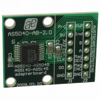
AS5140 AB
Description
BOARD ADAPTER AS5140
Manufacturer
austriamicrosystems
Specifications of AS5140 AB
Sensor Type
Magnetic, Rotary Position
Sensing Range
360°
Interface
Serial
Voltage - Supply
5V
Embedded
No
Utilized Ic / Part
AS5140
Lead Free Status / RoHS Status
Lead free by exemption / RoHS compliant by exemption
Sensitivity
-
Other names
AS5140H AB
AS5140H AB
AS5140H AB


AS5140H
Data Sheet - E l e c t r i c a l C h a r a c t e r i s t i c s
Table 12. Programming Conditions (Continued)
6.5 Timing Characteristics
T
Table 13. Synchronous Serial Interface (SSI)
Table 14. Pulse Width Modulation Output
Table 15. Incremental Outputs
www.austriamicrosystems.com/AS5140H
R
AMB
t
outputs valid
R
t
Incremental
unprogrammed
t
Symbol
Symbol
Symbol
DO tristate
t
PW
DO active
t
t
PW
programmed
t
T
Symbol
DO valid
CLK FE
Dir valid
CHARGE
f
f
t
f
t
PWM
f
f
CLK/2
WRITE
PROG
CSn
CLK
READ
LOAD
= -40 to +150ºC, VDD5V = 3.0-3.6V (3V operation) VDD5V = 4.5-5.5V (5V operation), unless otherwise noted.
MAX
MIN
Incremental outputs valid after power-up
Unprogrammed fuse resistance (log 0)
Programmed fuse resistance (log 1)
First data shifted to output register
Data output activated (logic high)
Programming time per bit
Directional indication valid
Maximum pulse width
Refresh time per bit
Minimum pulse width
Read-out frequency
WRITE frequency
Start of data output
Data output tristate
Pulse width of CSn
READ frequency
LOAD frequency
Data output valid
PWM frequency
Parameter
Parameter
Parameter
Parameter
Rising edge of CLK shifts out one bit at a
Signal period =1025µs ±10% at T
Time to charge the cap after t
Clock frequency to read out serial data
Signal period = 1025µs ±5% at T
Time between falling edge of CSn and
Time between falling edge of CSn and
Time between first falling edge of CSn
Time between rising edge of CLK and
CSn =high; To initiate read-out of next
Time between rising or falling edge of
After the last bit DO changes back to
Position 1023d; angle 359.65 degree
after power-up and valid incremental
10µA max. current @ 100mV
Time to prog. a singe fuse bit
Data can be loaded at n*2µs
2mA max. current @ 100mV
Read the data from the latch
LSB output and valid directional
Write the data to the latch
Position 0d; angle 0 degree
Revision 1.4
first falling edge of CLK
data output activated
data output valid
angular position
Conditions
-40 to +150ºC
Conditions
Conditions
Conditions
indication
“tristate”
outputs
25ºC
time
PROG
amb
amb
=
=
0.927
0.878
100k
0.90
Min
Min
500
500
500
Min
922
Min
50
10
>0
1
0.976
0.976
Typ
1024
Typ
Typ
Typ
1
1.024
1.074
1126
Max
Max
Max
1.10
Max
100
500
100
413
100
500
500
2.5
2.5
20
∞
1
Units
Units
Units
MHz
Units
kHz
MHz
MHz
10 - 37
µs
µs
kHz
ns
ns
ns
ns
ns
ns
ns
ns
µs
µs
Ω
Ω
Related parts for AS5140 AB
Image
Part Number
Description
Manufacturer
Datasheet
Request
R

Part Number:
Description:
BOARD DEMO AS5140
Manufacturer:
austriamicrosystems
Datasheet:

Part Number:
Description:
10-bit 360? Programmable Magnetic Rotary Encoder For High Ambient Temperatures Up To 150?c
Manufacturer:
austriamicrosystems
Datasheet:
Part Number:
Description:
IC SWITCH QUAD SPST 14-TSSOP
Manufacturer:
austriamicrosystems
Datasheet:
Part Number:
Description:
IC SWITCH QUAD SPST 14-TSSOP
Manufacturer:
austriamicrosystems
Datasheet:
Part Number:
Description:
IC AMP AUDIO MONO 1.8W 10-MSOP
Manufacturer:
austriamicrosystems
Datasheet:
Part Number:
Description:
IC AMP AUDIO MONO 1.8W 10-MSOP
Manufacturer:
austriamicrosystems
Datasheet:
Part Number:
Description:
IC AMP AUDIO MONO 1.8W 10-MSOP
Manufacturer:
austriamicrosystems
Datasheet:
Part Number:
Description:
IC AMP AUD 1.8W 3DB GAIN 10-MSOP
Manufacturer:
austriamicrosystems
Datasheet:
Part Number:
Description:
IC DRIVER LED 8-DIGIT 24-SOIC
Manufacturer:
austriamicrosystems
Datasheet:
Part Number:
Description:
IC DRIVER LED 8-DIGIT 24-SOIC
Manufacturer:
austriamicrosystems
Datasheet:
Part Number:
Description:
IC, LINE/SPEAKER PHONE CIRCUIT, SOIC-28
Manufacturer:
austriamicrosystems
Datasheet:
Part Number:
Description:
IC MULTI-STANDARD CMOS TELEPHONE SOIC-28
Manufacturer:
austriamicrosystems
Datasheet:
Part Number:
Description:
IC MULTI-STANDARD CMOS TELEPHONE SOIC-28
Manufacturer:
austriamicrosystems
Datasheet:
Part Number:
Description:
IC MULTI-STANDARD CMOS TELEPHONE SOIC-28
Manufacturer:
austriamicrosystems
Datasheet:
Part Number:
Description:
CABGA 64 (7x7)
Manufacturer:
austriamicrosystems
Datasheet: