AS5140 AB austriamicrosystems, AS5140 AB Datasheet - Page 13
AS5140 AB
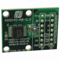
Manufacturer Part Number
AS5140 AB
Description
BOARD ADAPTER AS5140
Manufacturer
austriamicrosystems
Specifications of AS5140 AB
Sensor Type
Magnetic, Rotary Position
Sensing Range
360°
Interface
Serial
Voltage - Supply
5V
Embedded
No
Utilized Ic / Part
AS5140
Lead Free Status / RoHS Status
Lead free by exemption / RoHS compliant by exemption
Sensitivity
-
Other names
AS5140H AB
AS5140H AB
AS5140H AB


AS5140H
Data Sheet - D e t a i l e d D e s c r i p t i o n
Figure 5. Synchronous Serial Interface with Absolute Angular Position Data
Data Content
D9:D0 – Absolute angular position data (MSB is clocked out first).
OCF – (Offset Compensation Finished). Logic high indicates the finished Offset Compensation Algorithm. For fast startup, this bit may be polled
by the external microcontroller. As soon as this bit is set, the AS5140H has completed the startup and the data is valid
COF – (Cordic Overflow). Logic high indicates an out of range error in the CORDIC part. When this bit is set, the data at D9:D0 is invalid. The
absolute output maintains the last valid angular value. This alarm may be resolved by bringing the magnet within the X-Y-Z tolerance limits.
LIN – (Linearity Alarm). Logic high indicates that the input field generates a critical output linearity. When this bit is set, the data at D9:D0 may still
be used, but can contain invalid data. This warning may be resolved by bringing the magnet within the X-Y-Z tolerance limits.
MagINCn – (Magnitude Increase) becomes HIGH, when the magnet is pushed towards the IC, thus increasing the magnetic field strength.
MagDECn – (Magnitude Decrease) becomes HIGH, when the magnet is pulled away from the IC, thus decreasing the magnetic field strength.
Signal “HIGH” for both MagINCn and MagDECn indicate a magnetic field that is out of the allowed range
Table 16. Magnetic Magnitude Variation Indicator
Note: Pins 1 and 2 (MagINCn, MagDECn) are open drain outputs and require external pull-up resistors. If the magnetic field is in range, both
The two pins may also be combined with a single pull-up resistor. In this case, the signal is high when the magnetic field is in range. It is low in all
other cases
Even Parity – A bit for transmission error detection of bits 1to 15 (D9 to D0, OCF, COF, LIN, MagINCn, MagDECn).
The absolute angular output is always set to a resolution of 10 bit. Placing the magnet above the chip, angular values increase in clockwise
direction by default. Data D9:D0 is valid, when the status bits have the following configurations:
Table 17. Status Bit Outputs
www.austriamicrosystems.com/AS5140H
CSn
CLK
DO
OCF
MagINCn
outputs are turned off.
1
(see Table
0
0
1
1
t
DO active
t
CLK FE
16).
t
T
DO valid
CLK/2
COF
1
D9
0
MagDECn
D8
0
1
0
1
D7
D6
Angular Position Data
LIN
0
D5
No distance change
Magnetic Input Field OK (in range)
Distance increase: Pull-function. This state is dynamic, it is only active while the magnet
is moving away from the chip in Z-axis.
Distance decrease: Push- function. This state is dynamic, it is only active while the
magnet is moving towards the chip in Z.-axis.
Magnetic Input Field invalid – out of range: Too large, Too small (missing magnet).
D4
D3
MagINCn
8
D2
0
0
1
Revision 1.4
D1
D0
OCF COF
MagDECn
0
1
0
Status Bits
Description
LIN
Mag
INC
(see Table
Mag
DEC
even checksum of bits 1:15
16
Even
PAR
t
DO Tristate
t
16).
CSn
(see Table
Parity
t
CLK FE
17).
1
D9
13 - 37
Related parts for AS5140 AB
Image
Part Number
Description
Manufacturer
Datasheet
Request
R

Part Number:
Description:
BOARD DEMO AS5140
Manufacturer:
austriamicrosystems
Datasheet:

Part Number:
Description:
10-bit 360? Programmable Magnetic Rotary Encoder For High Ambient Temperatures Up To 150?c
Manufacturer:
austriamicrosystems
Datasheet:
Part Number:
Description:
IC SWITCH QUAD SPST 14-TSSOP
Manufacturer:
austriamicrosystems
Datasheet:
Part Number:
Description:
IC SWITCH QUAD SPST 14-TSSOP
Manufacturer:
austriamicrosystems
Datasheet:
Part Number:
Description:
IC AMP AUDIO MONO 1.8W 10-MSOP
Manufacturer:
austriamicrosystems
Datasheet:
Part Number:
Description:
IC AMP AUDIO MONO 1.8W 10-MSOP
Manufacturer:
austriamicrosystems
Datasheet:
Part Number:
Description:
IC AMP AUDIO MONO 1.8W 10-MSOP
Manufacturer:
austriamicrosystems
Datasheet:
Part Number:
Description:
IC AMP AUD 1.8W 3DB GAIN 10-MSOP
Manufacturer:
austriamicrosystems
Datasheet:
Part Number:
Description:
IC DRIVER LED 8-DIGIT 24-SOIC
Manufacturer:
austriamicrosystems
Datasheet:
Part Number:
Description:
IC DRIVER LED 8-DIGIT 24-SOIC
Manufacturer:
austriamicrosystems
Datasheet:
Part Number:
Description:
IC, LINE/SPEAKER PHONE CIRCUIT, SOIC-28
Manufacturer:
austriamicrosystems
Datasheet:
Part Number:
Description:
IC MULTI-STANDARD CMOS TELEPHONE SOIC-28
Manufacturer:
austriamicrosystems
Datasheet:
Part Number:
Description:
IC MULTI-STANDARD CMOS TELEPHONE SOIC-28
Manufacturer:
austriamicrosystems
Datasheet:
Part Number:
Description:
IC MULTI-STANDARD CMOS TELEPHONE SOIC-28
Manufacturer:
austriamicrosystems
Datasheet:
Part Number:
Description:
CABGA 64 (7x7)
Manufacturer:
austriamicrosystems
Datasheet: