AS5140 AB austriamicrosystems, AS5140 AB Datasheet - Page 21
AS5140 AB
Manufacturer Part Number
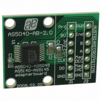
AS5140 AB
Description
BOARD ADAPTER AS5140
Manufacturer
austriamicrosystems
Specifications of AS5140 AB
Sensor Type
Magnetic, Rotary Position
Sensing Range
360°
Interface
Serial
Voltage - Supply
5V
Embedded
No
Utilized Ic / Part
AS5140
Lead Free Status / RoHS Status
Lead free by exemption / RoHS compliant by exemption
Sensitivity
-
Other names
AS5140H AB
AS5140H AB
AS5140H AB


AS5140H
Data Sheet - D e t a i l e d D e s c r i p t i o n
Figure 14. OTP Access Timing Diagram
7.6.6 Incremental Mode Programming
The following three different incremental output modes are available:
In both modes listed above, the incremental resolution may be reduced from 10 bit down to 9, 8 or 7 bit using the divider OTP bits Div1 and Div0
(see
To allow programming of all bits, the default factory setting is all bits = 0. This mode is equal to mode 1:0 (quadrature A/B, 1LSB index width,
256ppr). The absolute angular output value, by default, increases with clockwise rotation of the magnet (top view). Setting the CCW-bit
Table 19)
By default, the zero / index position pulse is one LSB wide. It can be increased to a three LSB wide pulse by setting the Index-bit of the OTP
register. Further programming options (commutation modes) are available for brushless DC motor-control.
Md1 = Md0 = 1 changes the incremental output pins 3, 4 and 6 to a 3-phase commutation signal. Div1 defines the number of pulses per
revolution for either a two-pole (Div1=0) or four-pole (Div1=1) rotor.
In addition, the LSB is available at pin 12 (the LSB signal replaces the PWM-signal), which allows for high rotational speed measurement of up to
10.000 rpm.
www.austriamicrosystems.com/AS5140H
- CCW = 0 – angular value increases clockwise;
- CCW = 1 – angular value increases counterclockwise.
Mode: Md1=0 / Md0=1 sets the AS5140H in quadrature mode.
Mode: Md1=1 / Md0=0 sets the AS5140H in step / direction mode
Mode: Md1=1 / Md0=1 sets the AS5140H in brushless DC motor commutation mode with an additional LSB incremental signal at pin 12
(PWM_LSB).
Table 20
PROG
CSn
CLK
allows for reversing the indicated direction, e.g. when the magnet is placed underneath the IC:
below).
Setup Condition
Operation Mode Selection
Revision 1.4
(see Table
2).
OTP Access
Exit Condition
(see
21 - 37
Related parts for AS5140 AB
Image
Part Number
Description
Manufacturer
Datasheet
Request
R

Part Number:
Description:
BOARD DEMO AS5140
Manufacturer:
austriamicrosystems
Datasheet:

Part Number:
Description:
10-bit 360? Programmable Magnetic Rotary Encoder For High Ambient Temperatures Up To 150?c
Manufacturer:
austriamicrosystems
Datasheet:
Part Number:
Description:
IC SWITCH QUAD SPST 14-TSSOP
Manufacturer:
austriamicrosystems
Datasheet:
Part Number:
Description:
IC SWITCH QUAD SPST 14-TSSOP
Manufacturer:
austriamicrosystems
Datasheet:
Part Number:
Description:
IC AMP AUDIO MONO 1.8W 10-MSOP
Manufacturer:
austriamicrosystems
Datasheet:
Part Number:
Description:
IC AMP AUDIO MONO 1.8W 10-MSOP
Manufacturer:
austriamicrosystems
Datasheet:
Part Number:
Description:
IC AMP AUDIO MONO 1.8W 10-MSOP
Manufacturer:
austriamicrosystems
Datasheet:
Part Number:
Description:
IC AMP AUD 1.8W 3DB GAIN 10-MSOP
Manufacturer:
austriamicrosystems
Datasheet:
Part Number:
Description:
IC DRIVER LED 8-DIGIT 24-SOIC
Manufacturer:
austriamicrosystems
Datasheet:
Part Number:
Description:
IC DRIVER LED 8-DIGIT 24-SOIC
Manufacturer:
austriamicrosystems
Datasheet:
Part Number:
Description:
IC, LINE/SPEAKER PHONE CIRCUIT, SOIC-28
Manufacturer:
austriamicrosystems
Datasheet:
Part Number:
Description:
IC MULTI-STANDARD CMOS TELEPHONE SOIC-28
Manufacturer:
austriamicrosystems
Datasheet:
Part Number:
Description:
IC MULTI-STANDARD CMOS TELEPHONE SOIC-28
Manufacturer:
austriamicrosystems
Datasheet:
Part Number:
Description:
IC MULTI-STANDARD CMOS TELEPHONE SOIC-28
Manufacturer:
austriamicrosystems
Datasheet:
Part Number:
Description:
CABGA 64 (7x7)
Manufacturer:
austriamicrosystems
Datasheet: