AS5140 AB austriamicrosystems, AS5140 AB Datasheet - Page 9
AS5140 AB
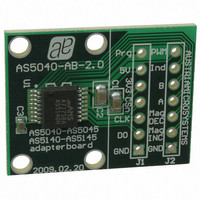
Manufacturer Part Number
AS5140 AB
Description
BOARD ADAPTER AS5140
Manufacturer
austriamicrosystems
Specifications of AS5140 AB
Sensor Type
Magnetic, Rotary Position
Sensing Range
360°
Interface
Serial
Voltage - Supply
5V
Embedded
No
Utilized Ic / Part
AS5140
Lead Free Status / RoHS Status
Lead free by exemption / RoHS compliant by exemption
Sensitivity
-
Other names
AS5140H AB
AS5140H AB
AS5140H AB


AS5140H
Data Sheet - E l e c t r i c a l C h a r a c t e r i s t i c s
Table 11. Electrical System Specifications (Continued)
1. Digital Interface
2. Integral Non-Linearity (INL) is the maximum deviation between actual position and indicated position.
3. Differential Non-Linearity (DNL) is the maximum deviation of the step length from one position to the next.
4. Transition Noise (TN) is the repeatability of an indicated position.
6.4 Programming Conditions
T
Table 12. Programming Conditions
www.austriamicrosystems.com/AS5140H
AMB
Symbol
Symbol
INL
V
V
INL
t
I
PwrUp
t
DNL
Hyst
CLK
ProgOff
PROG
LSB
delay
INL
V
V
PROG
TN
= -40 to 150ºC, VDD5V = 3.0-3.6V (3V operation) VDD5V = 4.5-5.5V (5V operation), unless otherwise noted.
f
temp
on
off
S
opt
On voltage; 300mV typ. hysteresis
Off voltage; 300mV typ. hysteresis
Sampling rate for absolute output
Integral non-linearity (optimum)
Integral non-linearity (optimum)
Programming voltage off level
Power-on reset thresholds
Power-on reset thresholds
System propagation delay
System propagation delay
Differential non-linearity
Integral non-linearity
Programming voltage
Programming current
Read-out frequency
incremental output
Transition noise
absolute output
Power-up time
Parameter
Hysteresis
Parameter
10 bit
7 bit
8 bit
9 bit
4
3
2
Max. clock frequency to read out serial data
Maximum error with respect to the best line
Maximum error with respect to the best line
diameter magnet, T
Verified at optimum magnet placement,
Verified at optimum magnet placement,
Over displacement tolerance with 6mm
Adjustable resolution only available for
Internal sampling rate, T
Internal sampling rate, T
Line must be discharged to this level
Voltage applied during programming
Least significant bit, minimum step
DC supply voltage 3.3V (VDD3V3)
Until offset compensation finished
Best line fit = (Err
Includes delay of ADC and DSP
Calculation over two samples
Current during programming
RMS equivalent to 1 sigma
incremental output modes;
Incremental modes only
10bit, no missing codes
T
AMB
Revision 1.4
(see Figure 3)
T
Conditions
Conditions
AMB
= -40 to +150ºC
+150ºC
fit.
fit.
AMB
=25ºC
max
= -40 to +150ºC
– Err
AMB
AMB
min
= -40 to
= 25ºC
) / 2
1.37
1.08
9.90
9.38
Min
Min
3.0
0
2.813
1.406
0.703
0.352
0.704
10.42
10.42
Typ
Typ
2.2
1.9
3.3
±0.176
10.94
11.46
Max
±0.5
±0.9
±1.4
0.12
Max
192
100
2.9
2.6
3.6
50
48
1
1
Units
Units
RMS
MHz
Deg
deg
deg
deg
deg
deg
deg
kHz
mA
ms
µs
µs
9 - 37
V
V
V
Related parts for AS5140 AB
Image
Part Number
Description
Manufacturer
Datasheet
Request
R

Part Number:
Description:
BOARD DEMO AS5140
Manufacturer:
austriamicrosystems
Datasheet:

Part Number:
Description:
10-bit 360? Programmable Magnetic Rotary Encoder For High Ambient Temperatures Up To 150?c
Manufacturer:
austriamicrosystems
Datasheet:
Part Number:
Description:
IC SWITCH QUAD SPST 14-TSSOP
Manufacturer:
austriamicrosystems
Datasheet:
Part Number:
Description:
IC SWITCH QUAD SPST 14-TSSOP
Manufacturer:
austriamicrosystems
Datasheet:
Part Number:
Description:
IC AMP AUDIO MONO 1.8W 10-MSOP
Manufacturer:
austriamicrosystems
Datasheet:
Part Number:
Description:
IC AMP AUDIO MONO 1.8W 10-MSOP
Manufacturer:
austriamicrosystems
Datasheet:
Part Number:
Description:
IC AMP AUDIO MONO 1.8W 10-MSOP
Manufacturer:
austriamicrosystems
Datasheet:
Part Number:
Description:
IC AMP AUD 1.8W 3DB GAIN 10-MSOP
Manufacturer:
austriamicrosystems
Datasheet:
Part Number:
Description:
IC DRIVER LED 8-DIGIT 24-SOIC
Manufacturer:
austriamicrosystems
Datasheet:
Part Number:
Description:
IC DRIVER LED 8-DIGIT 24-SOIC
Manufacturer:
austriamicrosystems
Datasheet:
Part Number:
Description:
IC, LINE/SPEAKER PHONE CIRCUIT, SOIC-28
Manufacturer:
austriamicrosystems
Datasheet:
Part Number:
Description:
IC MULTI-STANDARD CMOS TELEPHONE SOIC-28
Manufacturer:
austriamicrosystems
Datasheet:
Part Number:
Description:
IC MULTI-STANDARD CMOS TELEPHONE SOIC-28
Manufacturer:
austriamicrosystems
Datasheet:
Part Number:
Description:
IC MULTI-STANDARD CMOS TELEPHONE SOIC-28
Manufacturer:
austriamicrosystems
Datasheet:
Part Number:
Description:
CABGA 64 (7x7)
Manufacturer:
austriamicrosystems
Datasheet: