DM240312 Microchip Technology, DM240312 Datasheet - Page 13
DM240312
Manufacturer Part Number
DM240312
Description
BOARD DEV PIC24FJ256DA210
Manufacturer
Microchip Technology
Series
dsPIC™r
Type
MCUr
Specifications of DM240312
Contents
Board
Processor To Be Evaluated
PIC24FJ256DA210
Data Bus Width
16 bit
Interface Type
RS-232, USB, Ethernet, SPI, UART
Operating Supply Voltage
9 V to 15 V
Silicon Manufacturer
Microchip
Core Architecture
PIC
Core Sub-architecture
PIC24
Silicon Core Number
PIC24F
Silicon Family Name
PIC24FJxxDAxxx
Kit Contents
Board
Lead Free Status / RoHS Status
Lead free / RoHS Compliant
For Use With/related Products
PIC24FJ256DA210
Lead Free Status / Rohs Status
Lead free / RoHS Compliant
Available stocks
Company
Part Number
Manufacturer
Quantity
Price
Company:

Part Number:
DM240312
Manufacturer:
Microchip Technology
Quantity:
135
Company:
Part Number:
DM240312
Manufacturer:
MICROCHIP
Quantity:
12 000


1.3
2010 Microchip Technology Inc.
POWER REQUIREMENTS
1.2.1
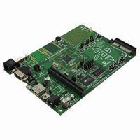
At the heart of the PIC24FJ256DA210 Development Board is the PIC24FJ256DA210
microcontroller. This microcontroller comes with a 16-bit core along with integrated
graphics controller, as well as a wide range of peripherals.
The graphics controller is capable of running TFT, MSTN and CSTN display panels with
resolution of up to QVGA (320x240) or WQVGA (480x272) at color depths of 16 bits
per pixel (bpp), and VGA (640x480) running at 8 bpp. QVGA resolution can be run with
the microcontroller’s internal 96 Kbyte of RAM at 8 bpp. Refer to the
“PIC24FJ256DA210 Family Data Sheet” (DS39969) for details.
1.2.2
The development board uses Microchip’s standardized 64-pin edge connector to
interface with compatible display boards. Both TFT and STN display boards can be
accommodated, as well as many forms of resistive touch screen interfaces. Please
refer to Section 4.4.4 “Graphics Port” for more details.
1.2.3
As part of its standard peripheral set, the PIC24FJ256DA210 microcontroller supports
full-speed USB operations with an on-chip controller and bus transceiver. In addition to
Device mode operations, the USB controller supports Host and On-The-Go (dual-role)
modes. The appropriate separate receptacles are provided for the required cable for
each mode. Note, however, that only one of the USB modes can be active at any time.
1.2.4
Beyond the graphics and USB interfaces, the development board is equipped with an
extensive set of additional features for hardware application development.
User-defined push button switches, CTMU-based touch sensors, LEDs, serial commu-
nications, and several varieties of external memory are provided to give the developer
a full range of hardware options. Please refer to Chapter 4. “Development Board
Hardware” for a complete discussion.
1.2.5
The PICtail Plus connector makes it possible to connect to a range of PICtail Plus
Daughter Boards, thus adding new functionality to an application under development.
The connector can be configured for different signal routings to accommodate different
daughter boards. Please refer to Section 4.4.6 “PICtail™ Plus Card Modular Expan-
sion Connector” for more information.
The PIC24FJ256DA210 Development Board can be powered from an external power
supply, or by applying power directly to test points on the board itself. For simplicity, an
unregulated 9V power supply is recommended (such as Microchip part number
AC162039).
Care must be observed when connecting customized displays. The on-board regula-
tors can supply up to 800 mA current combined. A separate external power supply may
be needed for bigger displays. Please refer the chosen display panel power
requirements for details.
PIC24FJ256DA210 Microcontroller
Graphics Interface
USB Options
Peripheral Options
PICtail Plus Connector
Introducing the Development Board
DS51911A-page 13
Related parts for DM240312
Image
Part Number
Description
Manufacturer
Datasheet
Request
R

Part Number:
Description:
Manufacturer:
Microchip Technology Inc.
Datasheet:
Part Number:
Description:
Manufacturer:
Microchip Technology Inc.
Datasheet:
Part Number:
Description:
Manufacturer:
Microchip Technology Inc.
Datasheet:
Part Number:
Description:
Manufacturer:
Microchip Technology Inc.
Datasheet:
Part Number:
Description:
Manufacturer:
Microchip Technology Inc.
Datasheet:
Part Number:
Description:
Manufacturer:
Microchip Technology Inc.
Datasheet:
Part Number:
Description:
Manufacturer:
Microchip Technology Inc.
Datasheet:
Part Number:
Description:
Manufacturer:
Microchip Technology Inc.
Datasheet: