DM240312 Microchip Technology, DM240312 Datasheet - Page 33
DM240312
Manufacturer Part Number
DM240312
Description
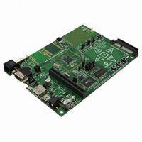
BOARD DEV PIC24FJ256DA210
Manufacturer
Microchip Technology
Series
dsPIC™r
Type
MCUr
Specifications of DM240312
Contents
Board
Processor To Be Evaluated
PIC24FJ256DA210
Data Bus Width
16 bit
Interface Type
RS-232, USB, Ethernet, SPI, UART
Operating Supply Voltage
9 V to 15 V
Silicon Manufacturer
Microchip
Core Architecture
PIC
Core Sub-architecture
PIC24
Silicon Core Number
PIC24F
Silicon Family Name
PIC24FJxxDAxxx
Kit Contents
Board
Lead Free Status / RoHS Status
Lead free / RoHS Compliant
For Use With/related Products
PIC24FJ256DA210
Lead Free Status / Rohs Status
Lead free / RoHS Compliant
Available stocks
Company
Part Number
Manufacturer
Quantity
Price
Company:

Part Number:
DM240312
Manufacturer:
Microchip Technology
Quantity:
135
Company:
Part Number:
DM240312
Manufacturer:
MICROCHIP
Quantity:
12 000


2010 Microchip Technology Inc.
4.3.3
The PIC24FJ256DA210 Development Board is equipped with two separate oscillator
circuits. The main oscillator uses an 8 MHz crystal (Y1) and functions as the controller’s
primary oscillator.
A second oscillator is implemented using a discrete oscillator circuit with a 32.768 kHz
(watch type) crystal (Y2). This is connected to the microcontroller’s SCLKI pin, provid-
ing an external clock source for the secondary oscillator option used to clock the RTCC
and Timer1 modules. A discrete oscillator is used in this application to free up an addi-
tional pin for general I/O use. To use this clock source, the microcontroller must be con-
figured to use External Clock mode for the secondary oscillator. For additional
information on secondary oscillator configuration, refer to the “PIC24FJ256DA210
Family Data Sheet” (DS39969).
4.3.4
The PIC24FJ256DA210 Development Board supports two power options.
In the first, an unregulated DC supply of 9V to 15V is supplied to J1. (A power supply
is not provided with the development board, unless the kit was purchased. If one is
required, Microchip Part number AC162039 is recommended). The 5V and 3.3V
regulators (Q1 and Q2, respectively) provide stable power to the board, as well as
compatible display daughter boards. Regulated 3.3V voltage is derived from the 5V
regulated voltage.
Optionally, an external, regulated DC power supply can be used to provide power to
the board. Two separate voltages are required: +5V (to TP3, the red terminal near the
upper left corner, adjacent to J9) and +3.3V (to TP4, the yellow terminal near the upper
right corner, adjacent to the prototype area).
The on-board voltage regulators can deliver a total combined current of 800 mA. If a
larger display with a current rating higher than 800 mA (combined board and display
rating) is to be used, the display board must be independently powered. In these cases,
power to the display cannot be provided through display connector V1. Only common
ground between the development board and the larger display should be connected
through V1.
A green power-on LED (D6) indicates when power is applied to the board from either
source. The power-on LED indicates the presence of +3.3V.
4.3.5
The PIC24FJ256DA210 Development Board can be programmed using either the
(PICkit) connector (J9) or the 5-wire, RJ-11 (ICD) connector (J10). Only one interface
may be used at any given time.
Use J9 to connect a PICkit 3 programmer, or other similar programmer/debugger
devices, to program the development board. Use J10 to program the board using the
MPLAB ICD 3 debugger or MPLAB REAL ICE in-circuit emulator.
4.3.6
Switch S4 is connected to the MCLR line of the microcontroller. When pressed, it pulls
the MCLR pin low, resetting the microcontroller (and any application the microcontroller
is running). The same reset signal is also connected to the Reset signals of the PICkit
and ICD connectors. However, any applications being run on PICtail daughter cards
installed in the PICtail Plus port will not be automatically reset. In these cases, the user
must provide an alternate hardware signal to the daughter board.
Oscillator Options
Power Supply
Programming and Debugging Interface
Reset Switch (S4)
Development Board Hardware
DS51911A-page 33
Related parts for DM240312
Image
Part Number
Description
Manufacturer
Datasheet
Request
R

Part Number:
Description:
Manufacturer:
Microchip Technology Inc.
Datasheet:
Part Number:
Description:
Manufacturer:
Microchip Technology Inc.
Datasheet:
Part Number:
Description:
Manufacturer:
Microchip Technology Inc.
Datasheet:
Part Number:
Description:
Manufacturer:
Microchip Technology Inc.
Datasheet:
Part Number:
Description:
Manufacturer:
Microchip Technology Inc.
Datasheet:
Part Number:
Description:
Manufacturer:
Microchip Technology Inc.
Datasheet:
Part Number:
Description:
Manufacturer:
Microchip Technology Inc.
Datasheet:
Part Number:
Description:
Manufacturer:
Microchip Technology Inc.
Datasheet: