DM240312 Microchip Technology, DM240312 Datasheet - Page 42
DM240312
Manufacturer Part Number
DM240312
Description
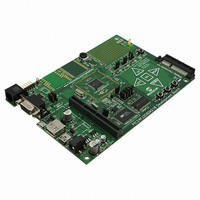
BOARD DEV PIC24FJ256DA210
Manufacturer
Microchip Technology
Series
dsPIC™r
Type
MCUr
Specifications of DM240312
Contents
Board
Processor To Be Evaluated
PIC24FJ256DA210
Data Bus Width
16 bit
Interface Type
RS-232, USB, Ethernet, SPI, UART
Operating Supply Voltage
9 V to 15 V
Silicon Manufacturer
Microchip
Core Architecture
PIC
Core Sub-architecture
PIC24
Silicon Core Number
PIC24F
Silicon Family Name
PIC24FJxxDAxxx
Kit Contents
Board
Lead Free Status / RoHS Status
Lead free / RoHS Compliant
For Use With/related Products
PIC24FJ256DA210
Lead Free Status / Rohs Status
Lead free / RoHS Compliant
Available stocks
Company
Part Number
Manufacturer
Quantity
Price
Company:

Part Number:
DM240312
Manufacturer:
Microchip Technology
Quantity:
135
Company:
Part Number:
DM240312
Manufacturer:
MICROCHIP
Quantity:
12 000


PIC24FJ256DA210 Development Board User’s Guide
DS51911A-page 42
4.4.4.3
The development board supports display panels with a built-in 4-wire resistive touch
screen. The resistive touch screen interface (X-, Y-, X+ and Y+) is used to directly con-
nect to the touch screen signals. X+ and Y+ are both analog and digital signals, and
are connected to I/O ports that can function both as analog inputs and digital outputs.
X- and Y- are digital output signals only, and are connected to digital I/O ports. The X+
and Y- signals are multiplexed with the SPI based touch screen controller.
When using the 4-wire resistive touch screen interface, jumpers JP9 and JP10 must be
set to their default positions, bridging pins 1 and 2 (Figure 4-7, callout 1).
4.4.4.4
Two SPI channels (two Chip Select lines) are provided in Display Connector V1 to
support display panels equipped with the following:
• SPI-Based Timing Controller: Some displays requires programming of an
• SPI-Based Touch Controller: In some cases, an SPI-based touch module is used
The SPI-based touch control features are configured by jumpers JP9 and JP10
(Figure 4-7, callout 1). To enable the use of an SPI-based touch controller, set jumpers
JP9 and JP10 to bridge positions 2-3.
FIGURE 4-7:
on-board Timing Controller (TCON) to initialize the settings of the display before it
is used. The TCON is used to synchronize the display glass timing with the dis-
play controller signal timing. This option is provided on the pins A27 (SPI_SCK),
A28 (SPI_MISO), B27 (DISP_SPI_CS) and B28 (SPI_MOSI) of display connector
V1.
with the display. Every time a touch is detected, it sends an interrupt to the host
controller to inform the host that there is a fresh touch input and the information
must be forwarded from the touch module to the host controller through SPI com-
munications. The development board shares two of the pins of the 4-wire resistive
touch screen with the interrupt and chip select line of the SPI based touch control-
ler. The sharing is done this way since in any system, only one of the two types of
user interface will be used.
Note:
1
RESISTIVE TOUCH SCREEN INTERFACE
SPI TOUCH CONTROLLER INTERFACE
As of this writing, none of the Microchip display boards support SPI-based
touch controllers.
TOUCH CONTROLLER AND BACKLIGHT CONFIGURATION
M
2010 Microchip Technology Inc.
2
Related parts for DM240312
Image
Part Number
Description
Manufacturer
Datasheet
Request
R

Part Number:
Description:
Manufacturer:
Microchip Technology Inc.
Datasheet:
Part Number:
Description:
Manufacturer:
Microchip Technology Inc.
Datasheet:
Part Number:
Description:
Manufacturer:
Microchip Technology Inc.
Datasheet:
Part Number:
Description:
Manufacturer:
Microchip Technology Inc.
Datasheet:
Part Number:
Description:
Manufacturer:
Microchip Technology Inc.
Datasheet:
Part Number:
Description:
Manufacturer:
Microchip Technology Inc.
Datasheet:
Part Number:
Description:
Manufacturer:
Microchip Technology Inc.
Datasheet:
Part Number:
Description:
Manufacturer:
Microchip Technology Inc.
Datasheet: