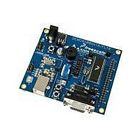
DEMO9S08FL16 Freescale Semiconductor, DEMO9S08FL16 Datasheet - Page 12
DEMO9S08FL16
Manufacturer Part Number
DEMO9S08FL16
Description
BOARD DEMO FOR FL16 FAMI
Manufacturer
Freescale Semiconductor
Type
MCUr
Datasheets
1.DEMO9S08FL16.pdf
(14 pages)
2.DEMO9S08FL16.pdf
(2 pages)
3.DEMO9S08FL16.pdf
(8 pages)
4.DEMO9S08FL16.pdf
(34 pages)
Specifications of DEMO9S08FL16
Contents
Board, Software
Processor To Be Evaluated
S08
Interface Type
RS-232
Operating Supply Voltage
12 V
For Use With/related Products
MC9S08FL16
Lead Free Status / RoHS Status
Lead free / RoHS Compliant
Available stocks
Company
Part Number
Manufacturer
Quantity
Price
Company:

Part Number:
DEMO9S08FL16
Manufacturer:
Freescal
Quantity:
12


U S E R
COM Connector
A standard 9-pin Dsub connector provides external connections for the SCI port. The Dsub
shell is connected to board ground through a ferrite bead. The ferrite bead provides noise
isolation on the RS-232 connection. Figure 6 below, shows the pin-out of the DB9 connector.
Figure 6: COM Connector
USER OPTIONS
The DEMO9S08SV16/FL16 includes various input and output devices to aid application
development and debug. User I/O includes 2 momentary pushbutton switches, 2 green LEDs,
1 potentiometer, 1 temperature sensor, and 1 piezo buzzer. Each device may be enabled or
disabled individually with the USER_EN option header. Each user enable is clearly marked as
to functionality.
Pushbutton Switches
Two push button switches provide momentary, active-low input, for user applications. Pull-ups
internal to the MCU must be enabled to provide error free switch operation. Pushbutton
switches SW1 and SW2 are enabled to the MCU I/O ports by the USER option bank. Table 2
below shows the user jumper settings and MCU connections.
LED Indicators
Two LEDs provide visual output for user applications. Both LEDs are configured for active-
high operation. Table 2 below shows the user jumper settings and MCU connections.
Potentiometer
A 5k ohm, thumb-wheel type, potentiometer at RV1 provides variable resistance input for user
applications. The output is the result of a voltage divider that changes as the thumb-wheel is
turned. The potentiometer is connected between VDD and GND with the center tap providing
the divider output. Table 2 below shows the user jumper settings and MCU connection.
4, 6
TXD
RXD
1, 6
GND
G U I D E
1
2
3
4
5
6
7
8
9
1, 4
RTS
CTS
NC
Female DB9 connector that interfaces to the HC(S)08 internal SCI1 serial
port via the U2 RS232 transceiver.
asynchronous serial communications without flow control. Flow control is
provided at test points on the board.
Pins 1, 4, and 6 are connected together.
12
It provides simple 2-wire
Related parts for DEMO9S08FL16
Image
Part Number
Description
Manufacturer
Datasheet
Request
R

Part Number:
Description:
Manufacturer:
Freescale Semiconductor, Inc
Datasheet:
Part Number:
Description:
Manufacturer:
Freescale Semiconductor, Inc
Datasheet:
Part Number:
Description:
Manufacturer:
Freescale Semiconductor, Inc
Datasheet:
Part Number:
Description:
Manufacturer:
Freescale Semiconductor, Inc
Datasheet:
Part Number:
Description:
Manufacturer:
Freescale Semiconductor, Inc
Datasheet:
Part Number:
Description:
Manufacturer:
Freescale Semiconductor, Inc
Datasheet:
Part Number:
Description:
Manufacturer:
Freescale Semiconductor, Inc
Datasheet:
Part Number:
Description:
Manufacturer:
Freescale Semiconductor, Inc
Datasheet:
Part Number:
Description:
Manufacturer:
Freescale Semiconductor, Inc
Datasheet:
Part Number:
Description:
Manufacturer:
Freescale Semiconductor, Inc
Datasheet:
Part Number:
Description:
Manufacturer:
Freescale Semiconductor, Inc
Datasheet:
Part Number:
Description:
Manufacturer:
Freescale Semiconductor, Inc
Datasheet:
Part Number:
Description:
Manufacturer:
Freescale Semiconductor, Inc
Datasheet:
Part Number:
Description:
Manufacturer:
Freescale Semiconductor, Inc
Datasheet:
Part Number:
Description:
Manufacturer:
Freescale Semiconductor, Inc
Datasheet: