DEMO9RS08KB12 Freescale Semiconductor, DEMO9RS08KB12 Datasheet - Page 10
DEMO9RS08KB12
Manufacturer Part Number
DEMO9RS08KB12
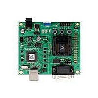
Description
DEMO BOARD FOR 9RS08KA12
Manufacturer
Freescale Semiconductor
Series
RS08r
Type
MCUr
Datasheets
1.DEMO9RS08KB12.pdf
(13 pages)
2.DEMO9RS08KB12.pdf
(48 pages)
3.DEMO9RS08KB12.pdf
(8 pages)
Specifications of DEMO9RS08KB12
Design Resources
DEMO9RS08KB12 Schematic
Contents
Board, Cable, DVD and Guide
Processor To Be Evaluated
RS08
Data Bus Width
8 bit, 10 bit
Operating Supply Voltage
- 0.3 V to + 5.8 V
Tool Type
Demonstration Board
Core Architecture
68RS08
Cpu Core
RS08
Silicon Manufacturer
Freescale
Core Sub-architecture
RS08
Silicon Core Number
MC9RS08
Silicon Family Name
RS08KB
Rohs Compliant
Yes
For Use With/related Products
MC9RS08KB12
Lead Free Status / RoHS Status
Lead free / RoHS Compliant


D E M O 9 S 0 8 K B 1 2
N O V E M B E R
1 6 ,
2 0 0 9
U S E R
G U I D E
RESET SWITCH
The RESET switch applies an asynchronous RESET to the MCU. The RESET switch is
connected directly to the RESET* input on the MCU. Pressing the RESET switch applies a
low voltage level to the RESET* input. A pull-up bias resistor ensures normal MCU operation.
Shunt capacitance ensures an adequate input pulse width.
The MC9RS08KB12 MCU applies a multiplexed RESET* input. To use the RESET switch, the
RESET pin must be enabled (SOPT1_RSTPE).
Refer to the MC9RS08KB12 Reference
Manual for details on configuring and using the RESET* input.
LOW VOLTAGE RESET
Both the MC9RS08KB12 apply an internal Low Voltage Detect (LVD) circuitry. The LVD holds
the MCU in reset until applied voltage reaches the appropriate level. The LVD also protects
against under-voltage conditions. Consult the MC9RS08KB12 Reference Manual for details
on LVD operation.
TIMING
Default timing for the DEMO9RS08KB12 is provided by the MC9RS08KB12 internal timing
source which is active out of RESET. External circuitry for an external 32 kHz XTAL oscillator
is provided; however, these components are not populated in default configuration.
Refer to
the MC9RS08KB12 Reference Manual for details on configuring the timing source.
COMMUNICATIONS
Serial communication on the DEMO9RS08KB12 board is supported through an RS-232
physical layer interface and DB-9 connector and through a virtual serial port implemented in
the USB-BDM. The COM_SEL option header selects between the applied serial function.
COM Port
An RS-232 transceiver provides RS-232 to TTL/CMOS logic level translation between the
COM connector and the MCU. The COM connector is a 9-pin Dsub, right-angle connector. A
ferrite bead on shield ground provides conducted immunity protection. Communication signals
TXD and RXD are routed from the transceiver to the MCU. These signals are also available
on connector J1. Hardware flow control signals RTS and CTS are available on the logic side
of the RS-232 transceiver and are routed to test point vias located near the transceiver. RTS
has been biased properly to provide handshaking if required.
RS-232 signals TXD and RXD are connected to the MCU through the COM_SEL option
header. Figure 5 below shows the RS-232 signal connections.
10
Related parts for DEMO9RS08KB12
Image
Part Number
Description
Manufacturer
Datasheet
Request
R

Part Number:
Description:
Manufacturer:
Freescale Semiconductor, Inc
Datasheet:
Part Number:
Description:
Manufacturer:
Freescale Semiconductor, Inc
Datasheet:
Part Number:
Description:
Manufacturer:
Freescale Semiconductor, Inc
Datasheet:
Part Number:
Description:
Manufacturer:
Freescale Semiconductor, Inc
Datasheet:
Part Number:
Description:
Manufacturer:
Freescale Semiconductor, Inc
Datasheet:
Part Number:
Description:
Manufacturer:
Freescale Semiconductor, Inc
Datasheet:
Part Number:
Description:
Manufacturer:
Freescale Semiconductor, Inc
Datasheet:
Part Number:
Description:
Manufacturer:
Freescale Semiconductor, Inc
Datasheet:
Part Number:
Description:
Manufacturer:
Freescale Semiconductor, Inc
Datasheet:
Part Number:
Description:
Manufacturer:
Freescale Semiconductor, Inc
Datasheet:
Part Number:
Description:
Manufacturer:
Freescale Semiconductor, Inc
Datasheet:
Part Number:
Description:
Manufacturer:
Freescale Semiconductor, Inc
Datasheet:
Part Number:
Description:
Manufacturer:
Freescale Semiconductor, Inc
Datasheet:
Part Number:
Description:
Manufacturer:
Freescale Semiconductor, Inc
Datasheet:
Part Number:
Description:
Manufacturer:
Freescale Semiconductor, Inc
Datasheet: