MPC8349EA-MDS-PB Freescale Semiconductor, MPC8349EA-MDS-PB Datasheet
MPC8349EA-MDS-PB
Specifications of MPC8349EA-MDS-PB


Related parts for MPC8349EA-MDS-PB


MPC8349EA-MDS-PB Summary of contents
Page 1
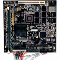
HW Getting Started Guide MPC8349E MDS Processor Board May 2005: rev 8 Step 1: Check HW kit contents. 1. MPC8349E MDS processor board 2. AC/DC 5V/5A universal power supply kit 3. RS232 standard serial cable with two 9-pin connectors—extends the ...
Page 2
Abbreviations and Definitions BCSR BMS CFG_RS CLKDIV CLKIN COP DDR DIP I2C © JTAG LED PCI PCI_SYNC_OUT PIB PLL RCW ROM SHMOO TLE TSEC 2 board control and status register boot memory space bit in RCW register clock division clock ...
Page 3
Step 2: Connect plastic spacers. Four sets of plastic spacers screw into holes located at (approximately) the four corners of the board. The spacers raise and stabilize the board. 1. From under the board, insert a male spacer into one ...
Page 4
Switches: SW3 Configuration Set 1 1: CFG_RS0 2: CFG_RS1 3: CFG_RS2 4: CLKDIV 5: SPMF0 6: SPMF1 7: SPMF2 8: SPMF3 1 <-> 0 Note! A DIP-switch in the ON position creates a zero-value signal. Switches: SW4 Configuration Set 2 ...
Page 5
Switches: SW7 Configuration Set 4 1: CORPLL0 2: CORPLL1 3: CORPLL2 4: CORPLL3 5: CORPLL4 6: CORPLL5 7: CORPLL6 8: COREDIS 1 <-> 0 Switches: SW2 Software Option Switches: SW5 Power Switch PCB ON Jumper: JP1 1 1 JP1 JP1 ...
Page 6
Step 4: Assemble and connect the power supply kit. Note! Move the power switch to OFF. Assemble the AC/DC power supply kit: • power cable with country-specific wall outlet plug • power supply unit and cable with jack (for board ...
Page 7
Step 7: Attach remaining cables to the board as per specifications. Connect the remaining cables to the board as per user specifications and planned board use: 1. JTAG/COP connector for JTAG connectivity unit—included in the CodeWarrior SW kit 2. Serial ...
Page 8
... All operating parameters, including “Typicals” must be validated for each customer application by customer’s technical experts. Freescale Semiconductor does not convey any license under its patent rights nor the rights of others. Freescale Semiconductor products are not designed, intended, or authorized for ...