101-1157 Rabbit Semiconductor, 101-1157 Datasheet
101-1157
Specifications of 101-1157


Related parts for 101-1157


101-1157 Summary of contents
Page 1
RabbitCore RCM4100 C-Programmable Core Module User’s Manual 019–0153 • 090508–G ...
Page 2
RabbitCore RCM4100 User’s Manual Part Number 019-0153 • 090508–G • Printed in U.S.A. ©2006–2009 Digi International Inc. • All rights reserved. No part of the contents of this manual may be reproduced or transmitted in any form or by any ...
Page 3
Chapter 1. Introduction 1.1 RCM4100 Features ...............................................................................................................................2 1.2 Advantages of the RCM4100 ...............................................................................................................4 1.3 Development and Evaluation Tools......................................................................................................5 1.3.1 RCM4110 Development Kit .........................................................................................................5 1.3.2 RCM4100 Analog Development Kit ............................................................................................6 1.3.3 Software ........................................................................................................................................6 1.3.4 Online Documentation ..................................................................................................................6 Chapter 2. Getting Started ...
Page 4
Other Hardware .................................................................................................................................. 41 4.5.1 Clock Doubler ............................................................................................................................ 41 4.5.2 Spectrum Spreader...................................................................................................................... 41 4.6 Memory .............................................................................................................................................. 42 4.6.1 SRAM......................................................................................................................................... 42 4.6.2 Flash EPROM............................................................................................................................. 42 Chapter 5. Software Reference 5.1 More About Dynamic C ..................................................................................................................... 43 5.2 Dynamic C Function ...
Page 5
The RCM4100 series is the first of the next-generation core modules that take advantage of new Rabbit as hardware DMA, clock speeds MHz, I/O lines shared with up to six serial ports and four levels of ...
Page 6
RCM4100 Features • Small size: 1.41" × 1.88" × 0.49" (36 mm × × 12 mm) • Microprocessor: Rabbit 4000 running 58.98 MHz • general-purpose I/O lines configurable with up to ...
Page 7
There are three RCM4100 production models. Table 1 summarizes their main features. Feature Microprocessor Flash Memory Data SRAM Fast Program-Execution SRAM A/D Converter 6 high-speed, CMOS- compatible ports: • all 6 configurable as asynchronous (with IrDA clocked serial ...
Page 8
Advantages of the RCM4100 • Fast time to market using a fully engineered, “ready-to-run/ready-to-program” micro- processor core. • Competitive pricing when compared with the alternative of purchasing and assembling individual components. • Easy C-language program development and debugging • ...
Page 9
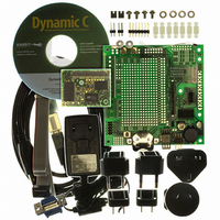
... CD. Install any Dynamic C modules after you the latest information on peripherals and accessories that install Dynamic C . are available for all RCM4100 RabbitCore module models. Rabbit and Dynamic C are registered trademarks of Rabbit Semiconductor Inc. Figure 1. RCM4110 Development Kit User’s Manual 5 ...
Page 10
RCM4100 Analog Development Kit The RCM4100 Analog Development Kit contains the hardware essentials you will need to use the RCM4100 module. The RCM4100 Analog Development Kit contents are similar to those of the RCM4110 Development Kit, except that the ...
Page 11
This chapter describes the RCM4100 series in more detail, and explains how to set up and use the accompanying Prototyping Board. NOTE: This chapter (and this manual) assume that you have the RCM4100 Development Kit. If you purchased an RCM4100 ...
Page 12
Hardware Connections There are three steps to connecting the Prototyping Board for use with Dynamic C and the sample programs: 1. Prepare the Prototyping Board for Development. 2. Attach the RCM4100 module to the Prototyping Board. 3. Connect the ...
Page 13
Step 2 — Attach Module to Prototyping Board Turn the RCM4100 module so that the mounting holes line up with the corresponding holes on the Prototyping Board. Insert the metal standoffs as shown, secure them from the bottom using ...
Page 14
Step 3 — Connect Programming Cable The programming cable connects the module to the PC running Dynamic C to download programs and to monitor the module during debugging. Connect the 10-pin connector of the programming cable labeled the RCM4100 ...
Page 15
If you are using a USB programming cable, your PC should recognize the new USB hard- ware, and the LEDs in the shrink-wrapped area of the programming cable will flash — if you get an error message, you will have ...
Page 16
Run a Sample Program Once the RCM4100/RCM4110 is connected as described in the preceding pages, start Dynamic C by double-clicking on the Dynamic C icon on your desktop or in your menu. If you are using a USB port ...
Page 17
Where From Here? If the sample program ran fine, you are now ready the sample programs in the RCM4100 User’s Manual (click the documentation icon on your PC) and to develop your ...
Page 18
RabbitCore RCM4100 ...
Page 19
R To develop and debug programs for the RCM4100 series (and for all other Rabbit hardware), you must install and use Dynamic C. This chapter provides a tour of its major features with respect to the RCM4100 series. 3.1 ...
Page 20
Sample Programs Of the many sample programs included with Dynamic C, several are specific to the RCM4100 series of modules. These programs will be found in the folder. —Demonstrates use of the digital outputs by having you turn LEDs ...
Page 21
RAM to reduce power • LOW_POWER.C consumption by the Rabbit microprocessor. There are four features that lead to the low- est possible power draw by the microprocessor. 1. Run the CPU from the ...
Page 22
Serial Communication The following sample programs are found in the —This program demonstrates how to configure Serial Port D for • FLOWCONTROL.C CTS/RTS with serial data coming from Serial Port C (TxC) at 115,200 bps. The serial data received ...
Page 23
RS-232 serial • SIMPLE3WIRE.C communication. Lower case characters are sent by TxC, and are received by RxD. The characters are converted to upper case and are sent out by TxD, are received by RxC, and are ...
Page 24
IOCONFIG_SWITCHECHO.C and F, which then transmit and then receive an ASCII string when switch pressed. The echoed serial data are displayed in the Dynamic C Note that the I/O lines that carry the Serial Port ...
Page 25
A/D Converter Inputs (RCM4100 only) The following sample programs are found in the AD_CAL_ALL.C —Demonstrates how to recalibrate all the single-ended analog input • channels with one gain using two known voltages to generate the calibration constants for each ...
Page 26
LN7 to calculate temperature • THERMISTOR.C for display to the Dynamic C thermistor is the one included in the Development Kit whose values for beta, series resistance, and resistance at standard temperature are given ...
Page 27
Baud rate 19,200 bps, 8 bits, no parity, 1 stop bit • Enable • Feed options — Follow the remaining steps carefully in Tera Term to avoid overwriting previously saved calibration data when using same the file name. • ...
Page 28
Real-Time Clock If you plan to use the real-time clock functionality in your application, you will need to set the real-time clock. Set the real-time clock using the the Dynamic C SAMPLES\RTCLOCK sample program in the Dynamic C RTC_TEST.C ...
Page 29
Chapter 4 describes the hardware components and principal hardware subsystems of the RCM4100 series. Appendix A, “RCM4100 Specifi- cations,” provides complete physical and electrical specifications. Figure 5 shows the Rabbit-based subsystems designed into the RCM4100. User’s Manual 4. H ARDWARE ...
Page 30
RCM4100 Digital Inputs and Outputs Figure 6 shows the RCM4100 series pinouts for header J2. Figure 6. RCM4100 Series Pinout standard 2 × 25 IDC header with a nominal 1.27 mm pitch. Headers RabbitCore RCM4100 ...
Page 31
Figure 7 shows the use of the Rabbit 4000 microprocessor ports in the RCM4100 series of modules. Figure 7. Use of Rabbit 4000 Ports The ports on the Rabbit 4000 microprocessor used in the RCM4100 series are config- urable, and ...
Page 32
Table 2. RCM4100 Series Pinout Configurations Pin Pin Name Default Use 1 +3.3 V_IN 2 GND 3 /RES_OUT Reset output 4 /IORD Output 5 /IOWR Output 6 /RESET_IN Input 7 VBAT_EXT Battery input 8–15 PA[0:7] Input/Output 16 PB0 Input/Output 17 ...
Page 33
Table 2. RCM4100 Series Pinout Configurations (continued) Pin Pin Name Default Use 24 PC0 Input/Output 25 PC1 Input/Output 26 PC2 Input/Output 27 PC3 Input/Output 28 PC4 Input/Output 29 PC5 Input/Output 30 PC6 Input/Output 31 PC7 Input/Output 32 PE0 Input/Output User’s ...
Page 34
Table 2. RCM4100 Series Pinout Configurations (continued) Pin Pin Name Default Use 33 PE1 Input/Output 34 PE2 Input/Output 35 PE3 Input/Output 36 PE4 Input/Output 37 PE5/SMODE0 Input/Output 38 PE6/SMODE1 Input/Output 39 PE7/STATUS Input/Output 30 Alternate Use I/O Strobe I1 Timer ...
Page 35
Table 2. RCM4100 Series Pinout Configurations (continued) Pin Pin Name Default Use 40 PD0 Input/Output 41 PD1 Input/Output 42 PD2 Input/Output 43 PD3 Input/Output 44 PD4 Input/Output 45 PD5 Input/Output 46 PD6 Input/Output 47 PD7 Input/Output User’s Manual Alternate Use ...
Page 36
Table 2. RCM4100 Series Pinout Configurations (continued) Pin Pin Name Default Use 40–47 LN[0:7] Analog Input 48 CONVERT/n.c. Digital Input Analog reference 49 VREF/n.c. voltage 50 GND Ground 4.1.1 Memory I/O Interface The Rabbit 4000 address lines (A0–A19) and all ...
Page 37
Serial Communication The RCM4100 series board does not have any serial driver or receiver chips directly on the board. However, an Ethernet or other serial interface may be incorporated on the board the RCM4100 is mounted on. For example, ...
Page 38
Table 3 summarizes the possible parallel port pins for the serial ports and their clocks. Table 3. Rabbit 4000 Serial Port and Clock Pins TXA PC6, PC7, PD6 Serial Port A RXA PC7, PD7, PE7 SCLKA PB1 TXB PC4, PC5, ...
Page 39
Programming Port The RCM4100 series of modules is programmed via the 10-pin header labeled J1. The programming port uses the Rabbit 4000’s Serial Port A for communication. Dynamic C uses the programming port to download and debug programs. Serial ...
Page 40
Programming Cable The programming cable is used to connect the programming port of the RCM4100 series of modules serial COM port. The programming cable converts the RS-232 voltage levels used by the PC serial port to ...
Page 41
A program “runs” in either mode, but can only be downloaded and debugged when the RCM4100 modules are in the Program Mode. Refer to the Rabbit 4000 Microprocessor User’s Manual gramming port. 4.3.2 Standalone Operation of the RCM4100 Once an ...
Page 42
A/D Converter (RCM4100 only) The RCM4100 has an onboard ADS7870 A/D converter whose scaling and filtering are done via the motherboard on which the RCM4100 module is mounted. The A/D converter multiplexes converted signals from eight single-ended or four ...
Page 43
If a device such as a battery is connected across two channels for a differential measurement, and it is not referenced to analog ground, then the current from the device will flow through both sets of attenuator resistors without flowing ...
Page 44
A/D Converter Power Supply The analog section is isolated from digital noise generated by other components by way of a low-pass filter composed of L1, C1, and C2 on the RCM4100 as shown in Figure 12. The +V analog ...
Page 45
Other Hardware 4.5.1 Clock Doubler The clock doubler on the RCM4100 is disabled by default. 4.5.2 Spectrum Spreader The Rabbit 4000 features a spectrum spreader, which helps to mitigate EMI problems. By default, the spectrum spreader is on automatically, ...
Page 46
Memory 4.6.1 SRAM RCM4100 series modules have 256K–512K of data SRAM installed at U10. In addition, the RCM4100 and RCM4120 have 512K of fast program-execution SRAM installed at U12. 4.6.2 Flash EPROM All RCM4100 modules also have 512K of ...
Page 47
Dynamic integrated development system for writing embedded software. It runs on an IBM-compatible PC and is designed for use with single-board computers and other devices based on the Rabbit microprocessor. Chapter 5 describes the libraries and function ...
Page 48
Dynamic C has a number of standard features. • Full-feature source and/or assembly-level debugger, no in-circuit emulator required. • Royalty-free TCP/IP stack with source code and most common protocols. • Hundreds of functions in source-code libraries and sample programs: Exceptionally ...
Page 49
Dynamic C Function Calls 5.2.1 Digital I/O The RCM4100 series of modules was designed to interface with other systems, and so there are no drivers written specifically for the I/O. The general Dynamic C read and write functions allow ...
Page 50
The sample code below shows how a protected variable is defined and how its value can be restored. main() { protected int state1, state2, state3; ... _sysIsSoftReset(); Additional information on protected Manual restore any protected variables variables is ...
Page 51
Prototyping Board Function Calls The functions described in this section are for use with the Prototyping Board features. The source code is in the Dynamic C library if you need to modify it for your own board design. NOTE: ...
Page 52
Alerts These function calls can be found in the Dynamic C library. RCM4xxx.LIB void timedAlert(unsigned long timeout); DESCRIPTION Polls the real-time clock until a timeout occurs. The RCM4100 series of RabbitCore modules will low-power mode during ...
Page 53
Analog Inputs (RCM4100 only) The function calls used with the Prototyping Board features and the A/D converter on the RCM4100 model are in the Dynamic C library. Dynamic C v. 10.07 or later is required to use the A/D ...
Page 54
PARAMETERS instructionbyte the instruction byte that will initiate a read or write operation bits on the designated register address. For example, the command data that configure the registers addressed by the in- cmd struction ...
Page 55
DESCRIPTION Reads the voltage of an analog input channel by serial-clocking an 8-bit command to the A/D converter by its Direct Mode method. This function assumes that Mode1 (most significant byte first) and the A/D converter ...
Page 56
Differential Input Channel Code Lines 0 +AIN0 -AIN1 1 +AIN2 -AIN3 2 +AIN4 -AIN5 † +AIN6 -AIN7 3 4 -AIN0 +AIN1 5 -AIN2 +AIN3 6 -AIN4 +AIN5 ‡ -AIN6 +AIN7 7 * Negative input is ground. † Not ...
Page 57
DESCRIPTION Reads the value of an analog input channel using the Direct Mode method of addressing the A/D converter. Note that it takes about 1 second to ensure an internal capacitor on ...
Page 58
RETURN VALUE A value corresponding to the voltage on the analog input channel: 0–2047 for single-ended conversions -2048–2047 for differential conversions ADTIMEOUT (-4095) if the conversion is incomplete or busy bit timeout ADOVERFLOW (-4096) for overflow or out of range ...
Page 59
DESCRIPTION Calibrates the response of the desired A/D converter channel as a linear function using the two conversion points provided. Four values are calculated and ...
Page 60
Prototyping Board): gaincode Gain Code Applies to Prototyping Board. the first A/D converter channel raw count value (0–2047) value1 ...
Page 61
DESCRIPTION Reads the state of a single-ended analog input channel and uses the previously set calibration constants to convert it to volts. PARAMETERS the channel number ( corresponding to LN0 to ...
Page 62
RETURN VALUE A voltage value corresponding to the voltage on the analog input channel. ADTIMEOUT (-4095) if the conversion is incomplete or busy bit timeout. ADOVERFLOW (-4096) for overflow or out of range. SEE ALSO anaInCalib, anaIn, anaInmAmps, ...
Page 63
DESCRIPTION Reads the state of differential analog input channels and uses the previously set calibra- tion constants to convert it to volts. PARAMETERS the channel number ( corresponding to LN0 to ...
Page 64
RETURN VALUE A voltage value corresponding to the voltage differential on the analog input channel. ADTIMEOUT (-4095) if the conversion is incomplete or busy bit timeout. ADOVERFLOW (-4096) for overflow or out of range. SEE ALSO anaInCalib, anaIn, ...
Page 65
DESCRIPTION Reads the state of an analog input channel and uses the previously set calibration con- stants to convert it to current. PARAMETERS the channel number ( corresponding to LN0 to LN7. channel RETURN ...
Page 66
DESCRIPTION Reads the calibration constants, gain, and offset for an input based on their designated position in the flash memory, and places them into global tables _adcCalibS, _adcCalibD, and ...
Page 67
The gaincode parameter is ignored when gaincode channel is ALLCHAN. Gain Code Applies to Prototyping Board. RETURN VALUE 0 if successful. -1 ...
Page 68
DESCRIPTION Writes the calibration constants, gain, and offset for an input based from global tables _adcCalibS, _adcCalibD, and _adcCalibM to designated positions in the flash memory. Depending on the flash size, ...
Page 69
The gaincode parameter is ignored when gaincode channel is ALLCHAN. Gain Code Applies to Prototyping Board. RETURN VALUE 0 if successful -1 ...
Page 70
Upgrading Dynamic C Dynamic C patches that focus on bug fixes are available from time to time. Check the Web site www.rabbit.com/support/ 5.3.1 Add-On Modules Starting with Dynamic C version 10.40, Dynamic C includes the popular µC/OS-II real- time ...
Page 71
A A. RCM4100 S PPENDIX Appendix A provides the specifications for the RCM4100 series of modules, and describes the conformal coating. User’s Manual PECIFICATIONS 67 ...
Page 72
A.1 Electrical and Mechanical Characteristics Figure A-1 shows the mechanical dimensions for the RCM4100 series of modules. Figure A-1. RCM4100 Dimensions NOTE: All measurements are in inches followed by millimeters enclosed in parentheses. All dimensions have a manufacturing tolerance of ...
Page 73
It is recommended that you allow for an “exclusion zone” of 0.04" (1 mm) around the RCM4100 modules in all directions when the RCM4100 is incorporated into an assembly that includes other printed circuit boards. An “exclusion zone” of 0.08" ...
Page 74
Table A-1 lists the electrical, mechanical, and environmental specifications for the RCM4100 series of modules. Table A-1. RCM4100 Specifications Parameter Microprocessor Flash Memory Data SRAM Fast Program-Execution SRAM Backup Battery 29 parallel digital I/0 lines: General Purpose I/O • configurable ...
Page 75
Table A-1. RCM4100 Specifications (continued) Parameter 6 high-speed, CMOS- compatible ports: • all 6 configurable as asynchronous (with IrDA clocked serial (SPI), and 2 as SDLC/HDLC Serial Ports • 1 asynchronous clocked serial port shared with program- ming ...
Page 76
A.1.1 A/D Converter Table A-2 shows some of the important A/D converter specifications. For more details, refer to the ADC7870 data sheet. Table A-2. A/D Converter Specifications Parameter Analog Input Characteristics Input Capacitance Input Impedance Common-Mode Differential Mode Static Accuracy ...
Page 77
A.1.2 Headers The RCM4100 series uses a header at J2 for physical connection to other boards × 25 SMT header with a 1.27 mm pin spacing. J1, the programming port × 5 header ...
Page 78
A.2 Rabbit 4000 DC Characteristics Table A-3. Rabbit 4000 Absolute Maximum Ratings Symbol T Operating Temperature A T Storage Temperature S V Maximum Input Voltage IH VDD Maximum Operating Voltage IO Stresses beyond those listed in Table A-3 may cause ...
Page 79
A.3 I/O Buffer Sourcing and Sinking Limit Unless otherwise specified, the Rabbit I/O buffers are capable of sourcing and sinking current per pin at full AC switching speed. Full AC switching assumes a 29.4 MHz CPU clock ...
Page 80
Figure A-4 shows a typical timing diagram for the Rabbit 4000 microprocessor external I/O read and write cycles. Figure A-4. External I/O Read and Write Cycles—No Extra Wait States NOTE: /IOCSx can be programmed to be active low (default) or ...
Page 81
Table A-7 lists the delays in gross memory access time for several values of VDD Table A-7. Preliminary Data and Clock Delays Clock to Address Output Delay VDD (ns ...
Page 82
A.5 Jumper Configurations Figure A-5 shows the header locations used to configure the various RCM4100 options via jumpers. Figure A-5. Location of RCM4100 Configurable Positions Table A-8 lists the configuration options. Table A-8. RCM4100 Jumper Configurations Header Description JP1 LN0 ...
Page 83
Table A-8. RCM4100 Jumper Configurations Header Description JP8 Data SRAM Size JP9 LN1 or PD1 on J2 pin 41 JP10 PE5 or SMODE0 Output on J2 JP11 PE6 or SMODE1 Output on J2 JP12 PE7 or STATUS Output on J2 ...
Page 84
A.6 Conformal Coating The areas around the 32 kHz real-time clock crystal oscillator have had the Dow Corning silicone-based 1-2620 conformal coating applied. The conformally coated area is shown in Figure A-6. The conformal coating protects these high-impedance circuits from ...
Page 85
A PPENDIX Appendix B describes the features and accessories of the Proto- typing Board, and explains the use of the Prototyping Board to demonstrate the RCM4100 series of modules and to build proto- types of your own circuits. The Prototyping ...
Page 86
B.1 Introduction The Prototyping Board included in the Development Kit makes it easy to connect an RCM4100 series module to a power supply and a PC workstation for development. It also provides some basic I/O peripherals (RS-232, LEDs, and switches), ...
Page 87
B.1.1 Prototyping Board Features —A a 3-pin header is provided for connection to the power supply. Power Connection • Note that the 3-pin header is symmetrical, with both outer pins connected to ground and the center pin connected to the ...
Page 88
Current Measurement Option • bottom side of the Prototyping Board and install a 1 × 2 header strip from the Develop- ment Kit to allow you to use an ammeter across the pins to measure the current drawn from the ...
Page 89
B.2 Mechanical Dimensions and Layout Figure B-2 shows the mechanical dimensions and layout for the Prototyping Board. Figure B-2. Prototyping Board Dimensions User’s Manual 85 ...
Page 90
Table B-1 lists the electrical, mechanical, and environmental specifications for the Proto- typing Board. Table B-1. Prototyping Board Specifications Parameter Board Size Operating Temperature Humidity Input Voltage Maximum Current Draw (including user-added circuits) Prototyping Area Connectors B.3 Power Supply The ...
Page 91
B.4 Using the Prototyping Board The Prototyping Board is actually both a demonstration board and a prototyping board demonstration board, it can be used to demonstrate the functionality of the RCM4100 series of modules right out of the ...
Page 92
Selected signals from the Rabbit 4000 microprocessor are available on header J2 of the Prototyping Board. The remaining ports on the Rabbit 4000 microprocessor are used for RS-232 serial communication. Table B-2 lists the signals on header J2 and explains ...
Page 93
B.4.1 Adding Other Components There are pads for 28-pin TSSOP devices, 16-pin SOIC devices, and 6-pin SOT devices that can be used for surface-mount prototyping with these devices. There are also pads that can be used for SMT resistors and ...
Page 94
B.4.3 Analog Features (RCM4100 only) The Prototyping Board has typical support circuitry installed to complement the ADS7870 A/D converter on the RCM4100 model (the A/D converter is not available on the RCM4110 and the RCM4120). B.4.3.1 A/D Converter Inputs Figure ...
Page 95
Many other possible ranges are possible by physically changing the resistor values that make up the attenuator circuit. NOTE: Analog input LN7_IN does not have the 10 kΩ resistor installed, and so no resistor attenuator is available, limiting its maximum ...
Page 96
B.4.3.2 Thermistor Input Analog input LN7_IN on the Prototyping Board was designed specifically for use with a thermistor at JP25 in conjunction with the strates how to use the analog input to measure temperature, which will be displayed in the ...
Page 97
B.4.4 Serial Communication The Prototyping Board allows you to access five of the serial ports from the RCM4100 series of modules. Table B-5 summarizes the configuration options. Note that Serial Ports E and F can be used only with the ...
Page 98
B.4.4.1 RS-232 RS-232 serial communication on header J4 on both Prototyping Boards is supported by an RS-232 transceiver installed at U3. This transceiver provides the voltage output, slew rate, and input voltage immunity required to meet the RS-232 serial communication ...
Page 99
B.5 Prototyping Board Jumper Configurations Figure B-8 shows the header locations used to configure the various Prototyping Board options via jumpers. Figure B-8. Location of Configurable Jumpers on Prototyping Board Table B-6 lists the configuration options using either jumpers or ...
Page 100
Table B-6. Prototyping Board Jumper Configurations (continued) Header Description JP5 PC1/RxD/Switch S2 JP6 JP7 PC2/TxC/LED DS3 JP8 JP9 PC3/RxC/Switch S3 JP10 JP11 LN0 buffer/filter to RCM4100 JP12 PB2/LED DS2 JP13 LN1 buffer/filter to RCM4100 JP14 PB3/LED DS3 JP15 LN2 buffer/filter ...
Page 101
Table B-6. Prototyping Board Jumper Configurations (continued) Header Description JP23 LN4_IN–LN6_IN JP24 LN0_IN–LN3_IN JP25 Thermistor Location NOTE: Jumper connections JP3–JP10, JP12, JP14, JP16, JP18, JP23, and JP24 are made using 0 Ω surface-mounted resistors. Jumper connections JP11, JP13, JP15, JP17, ...
Page 102
RabbitCore RCM4100 ...
Page 103
A Appendix C provides information on the current requirements of the RCM4100 series of modules, and includes some background on the chip select circuit used in power management. C.1 Power Supplies The RCM4100 series of modules requires a regulated 3.0 ...
Page 104
The drain on the battery by the RCM4110 is typically 7.5 µA when no other power is sup- plied 165 mA·h battery is used, the battery can last about 2.5 years: 165 mA·h ----------------------- - = 2.5 years. ...
Page 105
... V, exercise care when operating close to the 3.0 V minimum voltage (for example, keep the power supply as close as possible to the RCM4100) since your RCM4100 could reset unintentionally. The RCM4100 modules have a reset output, pin 3 on header J2. User’s Manual 101 ...
Page 106
RabbitCore RCM4100 ...
Page 107
A A/D converter access via Prototyping Board ....................................... 90 function calls anaIn .............................. 53 anaInCalib ..................... 55 anaInConfig ................... 49 anaInDiff ....................... 59 anaInDriver ................... 51 anaInEERd .................... 62 anaInEEWr .................... 64 anaInmAmps ................. 61 anaInVolts ..................... 57 inputs differential ...
Page 108
Prototyping Board (cont’d) JP20 (LN5 buffer/filter to RCM4100) ..................96 JP21 (LN6 buffer/filter to RCM4100) ..................96 JP22 (LN7 buffer/filter to RCM4100) ..................96 JP23 (analog inputs LN4– LN6 configuration) .....97 JP24 (analog inputs LN0– LN3 configuration) .....97 JP3–JP4 (PC0/TxD/LED DS2) ...
Page 109
A/D converter chip ............ 72 bus loading ........................ 75 digital I/O buffer sourcing and sinking limits ................ 75 dimensions ........................ 68 electrical, mechanical, and environmental ............... 70 exclusion zone ................... 69 header footprint ................. 73 Prototyping Board ...
Page 110
RabbitCore RCM4100 ...
Page 111
RCM4100 Schematic www.rabbit.com/documentation/schemat/090-0228.pdf 090-0230 Prototyping Board Schematic www.rabbit.com/documentation/schemat/090-0230.pdf 090-0128 Programming Cable Schematic www.rabbit.com/documentation/schemat/090-0128.pdf 090-0252 USB Programming Cable Schematic www.rabbit.com/documentation/schemat/090-0252.pdf You may use the URL information provided above to access the latest schematics directly. User’s Manual S CHEMATICS 107 ...
Page 112
...