EVAL6599-200W STMicroelectronics, EVAL6599-200W Datasheet - Page 23
EVAL6599-200W
Manufacturer Part Number
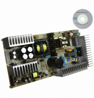
EVAL6599-200W
Description
EVAL BOARD FOR L6599
Manufacturer
STMicroelectronics
Type
Power Factor Correctionr
Specifications of EVAL6599-200W
Main Purpose
AC/DC, Primary Side and PFC
Outputs And Type
4, Isolated
Power - Output
200W
Voltage - Output
24V, 12V, 5V, 3.3V
Current - Output
6A, 5A, 1A, 700mA
Voltage - Input
90 ~ 264VAC
Regulator Topology
Resonant
Frequency - Switching
95kHz
Board Type
Fully Populated
Utilized Ic / Part
L6563, L6599
Input Voltage
90 V to 264 V
Output Voltage
3.3 V to 24 V
Dimensions
132 mm x 265 mm
Product
Power Management Modules
Lead Free Status / RoHS Status
Lead free / RoHS Compliant
For Use With/related Products
L6599
Other names
497-5496


L6599
7.4
Current sense, OCP and OLP
The resonant half-bridge is essentially voltage-mode controlled; hence a current sense input
will only serve as an overcurrent protection (OCP).
Unlike PWM-controlled converters, where energy flow is controlled by the duty cycle of the
primary switch (or switches), in a resonant half-bridge the duty cycle is fixed and energy flow
is controlled by its switching frequency. This impacts on the way current limitation can be
realized. While in PWM-controlled converters energy flow can be limited simply by
terminating switch conduction beforehand when the sensed current exceeds a preset
threshold (this is commonly now as cycle-by-cycle limitation), in a resonant half-bridge the
switching frequency, that is, its oscillator's frequency must be increased and this cannot be
done as quickly as turning off a switch: it takes at least the next oscillator cycle to see the
frequency change. This implies that to have an effective increase, able to change the energy
flow significantly, the rate of change of the frequency must be slower than the frequency
itself. This, in turn, implies that cycle-by-cycle limitation is not feasible and that, therefore,
the information on the primary current fed to the current sensing input must be somehow
averaged. Of course, the averaging time must not be too long to prevent the primary current
from reaching too high values.
In
described in the following. The circuit of
resistor Rs might not be negligible, hurting efficiency; the circuit of
complex but virtually lossless and recommended when the efficiency target is very high.
Figure 30. Current sensing technique with sense resistor
Figure 30 and Figure 31
L6599
6
a couple of current sensing methods are illustrated that will be
ISEN
τ
≈
f
10
min
Figure 30
Rs
Cr
is simpler but the dissipation on the sense
I
Cr
Vspk
0
Application information
Figure 31
is more
L6599
23/36
6
Related parts for EVAL6599-200W
Image
Part Number
Description
Manufacturer
Datasheet
Request
R

Part Number:
Description:
EVAL BOARD FOR L6599
Manufacturer:
STMicroelectronics
Datasheet:

Part Number:
Description:
DEMO BOARD FOR L6599
Manufacturer:
STMicroelectronics
Datasheet:

Part Number:
Description:
DEMO BOARD FOR L6599
Manufacturer:
STMicroelectronics
Datasheet:

Part Number:
Description:
STMicroelectronics [RIPPLE-CARRY BINARY COUNTER/DIVIDERS]
Manufacturer:
STMicroelectronics
Datasheet:
Part Number:
Description:
STMicroelectronics [LIQUID-CRYSTAL DISPLAY DRIVERS]
Manufacturer:
STMicroelectronics
Datasheet:

Part Number:
Description:
BOARD EVAL FOR MEMS SENSORS
Manufacturer:
STMicroelectronics
Datasheet:
Part Number:
Description:
NPN TRANSISTOR POWER MODULE
Manufacturer:
STMicroelectronics
Datasheet:
Part Number:
Description:
TURBOSWITCH ULTRA-FAST HIGH VOLTAGE DIODE
Manufacturer:
STMicroelectronics
Datasheet:
Part Number:
Description:
Manufacturer:
STMicroelectronics
Datasheet:
Part Number:
Description:
DIODE / SCR MODULE
Manufacturer:
STMicroelectronics
Datasheet:
Part Number:
Description:
DIODE / SCR MODULE
Manufacturer:
STMicroelectronics
Datasheet:
Part Number:
Description:
Search -----> STE16N100
Manufacturer:
STMicroelectronics
Datasheet: