G6KU-2G-Y DC5 Omron, G6KU-2G-Y DC5 Datasheet - Page 10
G6KU-2G-Y DC5
Manufacturer Part Number
G6KU-2G-Y DC5
Description
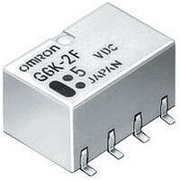
RELAY LOW SIGNAL SMD
Manufacturer
Omron
Series
G6Kr
Specifications of G6KU-2G-Y DC5
Coil Type
Latching, Single Coil
Coil Current
21.1mA
Relay Type
Telecom
Circuit
DPDT (2 Form C)
Contact Rating @ Voltage
1A @ 30VDC
Coil Voltage
5VDC
Control On Voltage (max)
3.75 VDC
Mounting Type
Surface Mount
Termination Style
J Lead
Contact Configuration
DPDT
Contact Current Max
1A
Contact Voltage Ac Nom
125V
Contact Voltage Dc Nom
30V
Coil Voltage Vdc Nom
5V
Coil Resistance
237ohm
Contact Form
DPDT (2 Form C)
Contact Rating (current)
1A
Switching Voltage
125VAC, 60VDC - Max
Turn On Voltage (max)
3.75 VDC
Turn Off Voltage (min)
-
Features
-
Contact Material
Silver (Ag), Gold (Au)
Operate Time
3ms
Release Time
3ms
Coil Power
100 mW
Operating Temperature
-40°C ~ 70°C
Lead Free Status / RoHS Status
Lead free / RoHS Compliant
Control Off Voltage (min)
-
Lead Free Status / Rohs Status
Lead free / RoHS Compliant
Other names
G6KU-2G-YDC5
G6KU2GYDC5
G6KU2GYDC5


G6K
Precautions
Refer to PCB Relays Catalog (X033) for information on general precautions. Be sure to read these precautions before using the Relay.
Correct Use
Long-term Continuously ON Contacts
Using the Relay in a circuit where the Relay will be ON continu-
ously for long periods (without switching) can lead to unstable
contacts because the heat generated by the coil itself will affect
the insulation, causing a film to develop on the contact surfaces.
We recommend using a latching relay (magnetic-holding relay) in
this kind of circuit. If a single-side stable model must be used in
this kind of circuit, we recommend using a fail-safe circuit design
that provides protection against contact failure or coil burnout.
Relay Handling
Use the Relay as soon as possible after opening the moisture-
proof package. If the Relay is left for a long time after opening the
moisture-proof package, the appearance may suffer and seal fail-
ure may occur after the solder mounting process. To store the
Relay after opening the moisture-proof package, place it into the
original package and sealed the package with adhesive tape.
When washing the product after soldering the Relay to a PCB,
use a water-based solvent or alcohol-based solvent, and keep the
solvent temperature to less than 40°C. Do not put the Relay in a
cold cleaning bath immediately after soldering.
Soldering
Soldering temperature: Approx. 250°C (260°C if the DWS method
is used)
Soldering time: Approx. 5 s max. (approx. 2 s for the first time and
approx. 3 s for the second time if the DWS method is used)
Be sure to adjust the level of the molten solder so that the solder
will not overflow onto the PCB.
Claw Securing Force During Automatic Mounting
During automatic insertion of Relays, make sure to set the secur-
ing force of each claw to the following so that the Relays charac-
teristics will be maintained.
Environmental Conditions During Operation, Storage, and
Transportation
Protect the Relay from direct sunlight and keep the Relay under
normal temperature, humidity, and pressure.
If the Relay is stored for a long time in an adverse environment
with high temperature, high humidity, organic gases, or sulfide
gases, sulfide or oxide films will form on the contact surfaces.
These films may result in unstable contact, contact problems, or
functional problems. Therefore, operate, store, or transport the
product under specified environmental conditions.
10
Direction A: 1.96 N
Direction B: 4.90 N
Direction C: 1.96 N
Latching Relay Mounting
Make sure that the vibration or shock that is generated from other
devices, such as relays in operation, on the same panel and
imposed on the Latching Relay does not exceed the rated value,
otherwise the Latching Relay that has been set may be reset or
vice versa. The Latching Relay is reset before shipping. If exces-
sive vibration or shock is imposed, however, the Latching Relay
may be set accidentally. Be sure to apply a reset signal before
use.
Maximum Allowable Voltage
The maximum allowable voltage of the coil can be obtained from
the coil temperature increase and the heat-resisting temperature
of coil insulating sheath material. (Exceeding the heat-resisting
temperature may result in burning or short-circuiting.) The maxi-
mum allowable voltage also involves important restrictions which
include the following:
• Must not cause thermal changes in or deterioration of the insu-
• Must not cause damage to other control devices.
• Must not cause any harmful effect on people.
• Must not cause fire.
Therefore, be sure to use the maximum allowable voltage beyond
the value specified in the catalog.
As a rule, the rated voltage must be applied to the coil. A voltage
exceeding the rated value, however, can be applied to the coil
provided that the voltage is less than the maximum allowable volt-
age. It must be noted that continuous voltage application to the
coil will cause a coil temperature increase thus affecting charac-
teristics such as electrical life and resulting in the deterioration of
coil insulation.
Coating
The Relay mounted on the PCB may be coated or washed but do
not apply silicone coating or detergent containing silicone, other-
wise the silicone coating or detergent may remain on the surface
of the Relay.
PCB Mounting
If two or more Relays are closely mounted with the long sides of
the Relays facing each other and soldering is performed with
infrared radiation, the solder may not be properly exposed to the
infrared rays. Be sure to keep the proper distance between adja-
cent Relays as shown below.
Two or more Relays may be closely mounted with the short sides
of the Relays facing each other.
G6K-2G
G6K-2F
lating material.
2 mm min.
2.7 mm min.
G6K
Related parts for G6KU-2G-Y DC5
Image
Part Number
Description
Manufacturer
Datasheet
Request
R

Part Number:
Description:
SURFACE MOUNT RELAY
Manufacturer:
Omron
Datasheet:
Part Number:
Description:
SURFACE MOUNT RELAY
Manufacturer:
Omron
Datasheet:
Part Number:
Description:
SURFACE MOUNT RELAY
Manufacturer:
Omron
Datasheet:
Part Number:
Description:
SMT Tape & Reel Relay
Manufacturer:
Omron
Datasheet:
Part Number:
Description:
SMT TAPE-N-REEL RELAY
Manufacturer:
Omron
Datasheet:
Part Number:
Description:
SMT TAPE-N-REEL RELAY
Manufacturer:
Omron
Datasheet:
Part Number:
Description:
SURFACE MOUNT RELAY
Manufacturer:
Omron
Datasheet:

Part Number:
Description:
SURFACE MOUNT RELAY
Manufacturer:
Omron
Datasheet:
Part Number:
Description:
SURFACE MOUNT RELAY
Manufacturer:
Omron
Datasheet: