G6KU-2G-Y DC5 Omron, G6KU-2G-Y DC5 Datasheet - Page 3
G6KU-2G-Y DC5
Manufacturer Part Number
G6KU-2G-Y DC5
Description
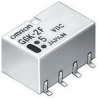
RELAY LOW SIGNAL SMD
Manufacturer
Omron
Series
G6Kr
Specifications of G6KU-2G-Y DC5
Coil Type
Latching, Single Coil
Coil Current
21.1mA
Relay Type
Telecom
Circuit
DPDT (2 Form C)
Contact Rating @ Voltage
1A @ 30VDC
Coil Voltage
5VDC
Control On Voltage (max)
3.75 VDC
Mounting Type
Surface Mount
Termination Style
J Lead
Contact Configuration
DPDT
Contact Current Max
1A
Contact Voltage Ac Nom
125V
Contact Voltage Dc Nom
30V
Coil Voltage Vdc Nom
5V
Coil Resistance
237ohm
Contact Form
DPDT (2 Form C)
Contact Rating (current)
1A
Switching Voltage
125VAC, 60VDC - Max
Turn On Voltage (max)
3.75 VDC
Turn Off Voltage (min)
-
Features
-
Contact Material
Silver (Ag), Gold (Au)
Operate Time
3ms
Release Time
3ms
Coil Power
100 mW
Operating Temperature
-40°C ~ 70°C
Lead Free Status / RoHS Status
Lead free / RoHS Compliant
Control Off Voltage (min)
-
Lead Free Status / Rohs Status
Lead free / RoHS Compliant
Other names
G6KU-2G-YDC5
G6KU2GYDC5
G6KU2GYDC5


G6K
■
■
Note:
Note:
Load
Rated load
Rated carry current
Max. switching voltage
Max. switching current
Contact resistance (See note 1.)
Operating (set) time (See note 2.)
Release (reset) time (See note 2.)
Insulation resistance (See note 3.) 1,000 M Ω min. (at 500 VDC)
Dielectric
strength
Impulse
withstand
voltage
Vibration resistance
Shock resistance
Endurance
Failure rate (P level) (See note 4.)
Ambient temperature
Ambient humidity
Weight
Contact Ratings
Characteristics
The above values are initial values.
1. The contact resistance was measured with 10 mA at 1 VDC with a voltage-drop method.
2. Values in parentheses are actual values.
3. The insulation resistance was measured with a 500-VDC megohmmeter applied to the same parts as those used for checking
4. This value was measured at a switching frequency of 120 operations/min and the criterion of contact resistance is 50 Ω . This
the dielectric strength.
value may vary depending on the switching frequency and operating environment. Always double-check relay suitability under
actual operating conditions.
Coil and contacts
Contacts of different
polarity
Contacts of same po-
larity
Coil and contacts
Contacts of different
polarity
Contacts of same po-
larity
Item
100 m Ω max.
3 ms max. (approx. 1.4 ms)
3 ms max. (approx. 1.3 ms)
1,500 VAC, 50/60 Hz for 1 min
1,000 VAC, 50/60 Hz for 1 min
750 VAC, 50/60 Hz for 1 min
1,500 V (10 x 160 µs)
1,500 V (10 x 160 µs)
Destruction: 10 to 55 Hz, 2.5-mm single amplitude (5-mm double amplitude) and 55 to 500 Hz,
300 m/s
Malfunction: 10 to 55 Hz, 1.65-mm single amplitude (3.3-mm double amplitude) and 55 to 500 Hz,
200 m/s
Destruction: 1,000 ms
Malfunction: 750 ms
Mechanical: 50,000,000 operations min. (at 36,000 operations/hour)
Electrical: 100,000 operations min. (with a rated load at 1,800 operations/hour)
10 µA at 10 mVDC
Operating: − 40°C to 70°C (with no icing or condensation)
Operating: 5% to 85%
Approx. 0.7 g
Resistive load
0.3 A at 125 VAC; 1 A at 30 VDC
1 A
125 VAC, 60 VDC
1 A
G6K-2F, G6K-2G, G6K-2P
2
2
(approx. 30G)
(approx. 20G)
Single-side stable models (double-pole)
2
(approx. 75G)
2
(approx. 100G)
2,500 V (2 x 10 µs), 1,500 V (10 x 160 µs)
G6K-2F-Y, G6K-2G-Y,
G6K-2P-Y
3 ms max. (approx. 1.2 ms)
3 ms max. (approx. 1.2 ms)
G6KU-2F-Y, G6KU-2G-Y,
Single-winding latching
G6KU-2P-Y
model
G6K
3
Related parts for G6KU-2G-Y DC5
Image
Part Number
Description
Manufacturer
Datasheet
Request
R

Part Number:
Description:
SURFACE MOUNT RELAY
Manufacturer:
Omron
Datasheet:
Part Number:
Description:
SURFACE MOUNT RELAY
Manufacturer:
Omron
Datasheet:
Part Number:
Description:
SURFACE MOUNT RELAY
Manufacturer:
Omron
Datasheet:
Part Number:
Description:
SMT Tape & Reel Relay
Manufacturer:
Omron
Datasheet:
Part Number:
Description:
SMT TAPE-N-REEL RELAY
Manufacturer:
Omron
Datasheet:
Part Number:
Description:
SMT TAPE-N-REEL RELAY
Manufacturer:
Omron
Datasheet:
Part Number:
Description:
SURFACE MOUNT RELAY
Manufacturer:
Omron
Datasheet:

Part Number:
Description:
SURFACE MOUNT RELAY
Manufacturer:
Omron
Datasheet:
Part Number:
Description:
SURFACE MOUNT RELAY
Manufacturer:
Omron
Datasheet: