G3NA-425B DC5-24 Omron, G3NA-425B DC5-24 Datasheet - Page 10
G3NA-425B DC5-24
Manufacturer Part Number
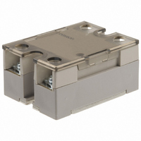
G3NA-425B DC5-24
Description
RELAY SSR 25A@440VAC ZERO CROSS
Manufacturer
Omron
Series
G3NAr
Specifications of G3NA-425B DC5-24
Circuit
SPST-NO (1 Form A)
Output Type
AC, Zero Cross
Load Current
25A
Voltage - Input
5 ~ 24VDC
Voltage - Load
180 ~ 528 V
Mounting Type
Chassis Mount
Termination Style
Screw Terminal
Package / Case
Hockey Puck
Control Voltage Range
5 VDC to 24 VDC
Load Voltage Rating
400 V to 600 V
Load Current Rating
25 A
Contact Form
1 Form A
Mounting Style
DIN Rail
Relay Type
General Purpose Hockey Puck
Lead Free Status / RoHS Status
Contains lead / RoHS non-compliant
On-state Resistance
-
Lead Free Status / Rohs Status
Lead free / RoHS Compliant
Other names
G3NA-425B-DC5-24
G3NA425BDC524
Z170
G3NA425BDC524
Z170


High-capacity Heat Sink (Y92B-P250N)
DIN-track Mounting
• Assembled DIN Tracks are heavy. Mount the DIN Tracks securely.
• Attach End Plates (PFP-M, order separately) to both ends of the
• To mount a Heat Sink to a DIN Track, press down at the point
Applicable DIN Track
Mounting is possible on TE35-15Fe (IEC 60715) DIN tracks. DIN
tracks from the following manufacturers can be used.
Direct Mounting
• Prepare mounting holes as shown in the diagram.
Operating Conditions
• Do not apply currents exceeding the rated current otherwise, the
• As protection against accidents due to short-circuiting, be sure to
• Do not apply overvoltages to the input circuit or output circuit.
• Do not drop the G3NA or otherwise subject it to abnormal shock.
• Keep the cooling system running continuously during the ON/OFF
476
Schneider
WAGO
PHOENIX
Be sure that the Heat Sink is securely locked to the DIN Track.
Units on the DIN Track to hold them in place.
indicated by arrow 1 in the diagram and then press in the Heat Sink
at the point indicated by arrow 2.
Tightening torque: 0.98 to 1.47 N·m
temperature of the G3NA may rise excessively.
install protective devices, such as fuses and no-fuse breakers, on
the power supply side.
Failure or burning may result.
Malfunction or failure may result.
operation of the SSR. This is to allow residual heat to dissipate
while the SSR is OFF.
Manufacturer
Solid State Relays (600 VAC Models)
AM1-DE2000
210-114 or 210-197
N35/15
Vertical
Thickness: 1.5 mm
130
±0.3
Four, 4.5 dia. or M4 holes
64
±0.3
---
210-118
N35/15/15-2.3
Thickness: 2.3 mm
G3NA-6
Noise Terminal Voltage According to
EN55011
The G3NA-UTU complies with EN55011 standards when a capacitor
is connected to the load power supply as shown in the following
circuit diagram.
• Connect capacitor C1 to both sides of the input terminals for a
• Connect capacitor C2 to both sides of the load power supply
• Connect the varistor to both sides of the G3NA output terminals.
• Do not use an input line that is longer than 3 m.
Loss Time
The loss time will increase when the G3NA is used at a low applied
voltage or current. Be sure that this does not cause any problems.
Using DC Loads
For a DC or L load, a diode should be connected in parallel the load
to absorb the counter electromotive force of the load.
G3NA with a DC input.
output.
Input
Capacitor C1
0.1 µF
C1
3 m max.
Input
G3NA-UTU
type
SSR
Loss time
Output
Varistor
•
G3NA-6@@: 910 V, 0.8 W
Load
C2
Load
Capacitor C2
•
G3NA-6@@: 0.5 µF, 500 VAC
Load power
supply
Related parts for G3NA-425B DC5-24
Image
Part Number
Description
Manufacturer
Datasheet
Request
R

Part Number:
Description:
RELAY SSR 25A@440VAC ZERO CROSS
Manufacturer:
Omron
Datasheet:


Part Number:
Description:
G6S-2GLow Signal Relay
Manufacturer:
Omron Corporation
Datasheet:
Part Number:
Description:
Compact, Low-cost, SSR Switching 5 to 20 A
Manufacturer:
Omron Corporation
Datasheet:
Part Number:
Description:
Manufacturer:
Omron Corporation
Datasheet:
Part Number:
Description:
Manufacturer:
Omron Corporation
Datasheet:
Part Number:
Description:
Manufacturer:
Omron Corporation
Datasheet:
Part Number:
Description:
Manufacturer:
Omron Corporation
Datasheet:
Part Number:
Description:
Manufacturer:
Omron Corporation
Datasheet: