G3NA-425B DC5-24 Omron, G3NA-425B DC5-24 Datasheet - Page 8
G3NA-425B DC5-24
Manufacturer Part Number
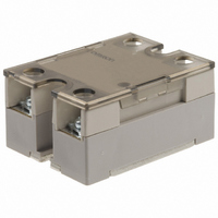
G3NA-425B DC5-24
Description
RELAY SSR 25A@440VAC ZERO CROSS
Manufacturer
Omron
Series
G3NAr
Specifications of G3NA-425B DC5-24
Circuit
SPST-NO (1 Form A)
Output Type
AC, Zero Cross
Load Current
25A
Voltage - Input
5 ~ 24VDC
Voltage - Load
180 ~ 528 V
Mounting Type
Chassis Mount
Termination Style
Screw Terminal
Package / Case
Hockey Puck
Control Voltage Range
5 VDC to 24 VDC
Load Voltage Rating
400 V to 600 V
Load Current Rating
25 A
Contact Form
1 Form A
Mounting Style
DIN Rail
Relay Type
General Purpose Hockey Puck
Lead Free Status / RoHS Status
Contains lead / RoHS non-compliant
On-state Resistance
-
Lead Free Status / Rohs Status
Lead free / RoHS Compliant
Other names
G3NA-425B-DC5-24
G3NA425BDC524
Z170
G3NA425BDC524
Z170


Safety Precautions
■ Precautions for Safe Use
Although OMRON continuously strives to improve the quality and
reliability of our relays, the G3NA contains semiconductors, which
are generally prone to occasional malfunction and failure.
Maintaining safety is particularly difficult if a relay is used outside of
its ratings. Always use the G3NA within the rated values. When using
the G3NA, always design the system to ensure safety and prevent
human accidents, fires, and social damage even in the event of
G3NA failure, including system redundancy, measures to prevent
fires from spreading, and designs to prevent malfunction.
1. G3NA malfunction or fire damage may occasionally occur. Do not
2. Heat Dissipation
474
Touching the charged section may occasionally cause
minor electric shock. Do not touch the G3NA terminal
section (the charged section) when the power supply
is ON. Be sure to attach the cover before use.
The G3NA and heat sink will be hot and may occasion-
ally cause minor burns. Do not touch the G3NA or the
heat sink either while the power supply is ON, or imme-
diately after the power is turned OFF.
The internal snubber circuit is charged and may occa-
sionally cause minor electric shock. Do not touch the
G3NA’s main circuit terminals immediately after the
power is turned OFF.
Be sure to conduct wiring with the power supply turned
OFF, and always attach the terminal cover after com-
pleting wiring. Touching the terminals when they are
charged may occasionally result in minor electric
shock.
Do not apply a short-circuit to the load side of the
G3NA. The G3NA may rupture. To protect against
short-circuit accidents, install a protective device, such
as a quick-burning fuse, on the power supply line.
apply excessive voltage or current to the G3NA terminals.
• Do not obstruct the airflow to the G3NA or heat sink. Heat
• Be sure to prevent the ambient temperature from rising due to
• Mount the G3NA in the specified orientation. If the G3NA is
• Do not use the G3NA if the heat sink fins are bent, e.g., as the
• Apply a thin layer of Toshiba Silicone’s YG6260 or Sinetsu
!CAUTION
!CAUTION
!CAUTION
!CAUTION
!CAUTION
generated from an G3NA error may occasionally cause the
output element to short, or cause fire damage.
the heat radiation of the G3NA. If the G3NA is mounted inside a
panel, install a fan so that the interior of the panel is fully
ventilated.
mounted in any other orientation, abnormal heat generation
may cause output elements to short or may cause burning.
result of dropping the G3NA. Heat dissipation characteristics will
be reduced, possibly causing G3NA failure.
Silicone’s G746, or a similar material to the heat sink before
mounting
Solid State Relays (600 VAC Models)
G3NA-6
3. Wire the G3NA and tighten screws correctly, observing the follow-
4. Operating Conditions
5. Do not transport the G3NA under the following conditions. Failure
• If a material with high thermal resistance, such as wood, is
• Use the specified heat sink or one with equivalent or better
ing precautions
Heat generated by a terminal error may occasionally result in fire
damage. Do not operate if the screws on the output terminal are
loose.
• Abnormal heat generated by wires may occasionally result in
• Abnormal heat generated by terminals may occasionally result
Tightening Torque
• Abnormal heat generated by terminals may occasionally result
• For G3NA Relays of 50 A or higher, use crimp terminals of an
• Use wires that are suitable for the load current and voltage.
• Do not use any wires with damaged sheaths. These may cause
• Do not place wiring in the same conduit or duct as high-voltage
• Use wires of an appropriate length, otherwise malfunction and
• Mount the DIN Track securely. Otherwise, the DIN Track may fall.
• Be sure that the G3NA clicks into place when mounting it to DIN
• Do not mount the G3NA when your hands are oily or dirty, e.g.,
• Tighten the G3NA screws securely.
• Abnormal heat generation may cause output elements to short
• Tighten the heat sink screws securely.
• The G3NA may fall if it is not mounted correctly.
• Only use the G3NA with loads that are within the rated values.
• Use a power supply within the rated frequency range. Using a
• Never apply voltage or current to the I/O terminals that exceeds
or malfunction may occur.
• Conditions under which the G3NA will be exposed to water
• High temperatures or high humidity
used, heat generated by the G3NA may occasionally cause fire
or burning. When installing the G3NA directly into a control
panel so that the panel can be used as a heat sink, use a panel
material with low thermal resistance, such as aluminum or steel.
characteristics. Abnormal heat generation may cause output
elements to short or may cause burning.
fire damage. Use wires suitable for the load current.
in fire damage. Do not operate if the screws on the output termi-
nal are loose.
in fire damage. When tightening terminal screws, be sure that
no non-conductive material is caught in screw.
appropriate size for the wire diameter for M5 terminals.
Abnormal heat generated by the wires may result in fire damage
or melting of the sheath, causing electric shock.
electric shock or leakage.
lines. Induction may cause malfunction or damage.
damage may result due to induction.
Track. The G3NA may fall if it is not mounted correctly.
with metal powder. These may cause G3NA failure.
Tightening torque: 0.78 to 0.98 N·m
or may cause burning.
Tightening torque: 0.98 to 1.47 N·m
Using the G3NA with loads outside the rated values may result
in malfunction, damage, or burning.
power supply outside the rated frequency range may result in
malfunction, damage, or burning.
the rated range. Doing so may result in malfunction, damage, or
burning.
M4
M5
Screw size
1.2 N·m
2.0 N·m
Tightening torque
Related parts for G3NA-425B DC5-24
Image
Part Number
Description
Manufacturer
Datasheet
Request
R

Part Number:
Description:
RELAY SSR 25A@440VAC ZERO CROSS
Manufacturer:
Omron
Datasheet:


Part Number:
Description:
G6S-2GLow Signal Relay
Manufacturer:
Omron Corporation
Datasheet:
Part Number:
Description:
Compact, Low-cost, SSR Switching 5 to 20 A
Manufacturer:
Omron Corporation
Datasheet:
Part Number:
Description:
Manufacturer:
Omron Corporation
Datasheet:
Part Number:
Description:
Manufacturer:
Omron Corporation
Datasheet:
Part Number:
Description:
Manufacturer:
Omron Corporation
Datasheet:
Part Number:
Description:
Manufacturer:
Omron Corporation
Datasheet:
Part Number:
Description:
Manufacturer:
Omron Corporation
Datasheet: