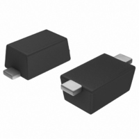
PTVS16VS1UR,115 NXP Semiconductors, PTVS16VS1UR,115 Datasheet - Page 4

PTVS16VS1UR,115
Manufacturer Part Number
PTVS16VS1UR,115
Description
TVS UNI-DIR 16V 400W SOD-123W
Manufacturer
NXP Semiconductors
Series
-r
Specifications of PTVS16VS1UR,115
Package / Case
SOD-123 Flat Leads
Voltage - Reverse Standoff (typ)
16V
Voltage - Breakdown
17.8V
Power (watts)
400W
Polarization
Unidirectional
Mounting Type
Surface Mount
Polarity
Unidirectional
Channels
1 Channel
Clamping Voltage
26 V
Operating Voltage
16 V
Breakdown Voltage
18.75 V
Peak Surge Current
15.4 A
Peak Pulse Power Dissipation
400 W
Maximum Operating Temperature
+ 150 C
Minimum Operating Temperature
- 55 C
Dimensions
1.9 mm W x 2.8 mm L
Number Of Elements
1
Package Type
SOD FlatPower
Operating Temperature Classification
Military
Reverse Breakdown Voltage
17.8V
Reverse Stand-off Voltage
16V
Leakage Current (max)
100nA
Peak Pulse Current
15.4A
Test Current (it)
1mA
Operating Temp Range
-55C to 150C
Mounting
Surface Mount
Pin Count
2
Lead Free Status / RoHS Status
Lead free / RoHS Compliant
Lead Free Status / RoHS Status
Lead free / RoHS Compliant, Lead free / RoHS Compliant
Other names
934061354115
NXP Semiconductors
6. Thermal characteristics
7. Characteristics
Table 9.
T
Table 10.
T
PTVSxS1UR_SER
Product data sheet
Type number
PTVS3V3S1UR
PTVS5V0S1UR
PTVS6V0S1UR
PTVS6V5S1UR
PTVS7V0S1UR
Type number
PTVS7V5S1UR
PTVS8V0S1UR
PTVS8V5S1UR
PTVS9V0S1UR
PTVS10VS1UR
PTVS11VS1UR
PTVS12VS1UR
PTVS13VS1UR
j
j
= 25
= 25
°
°
C unless otherwise specified.
C unless otherwise specified.
Characteristics per type; PTVS3V3S1UR to PTVS7V0S1UR
Characteristics per type; PTVS7V5S1UR to PTVS64VS1UR
Reverse standoff
voltage
V
Max
3.3
5.0
6.0
6.5
7.0
Reverse standoff
voltage
V
Max
7.5
8.0
8.5
9.0
10
11
12
13
RWM
RWM
Table 8.
[1]
[2]
[3]
[4]
Symbol
R
R
th(j-a)
th(j-sp)
(V)
(V)
Device mounted on an FR4 Printed-Circuit Board (PCB), single-sided copper, tin-plated and standard
footprint.
Device mounted on an FR4 PCB, single-sided copper, tin-plated, mounting pad for cathode 1 cm
Device mounted on a ceramic PCB, Al
Soldering point of cathode tab.
Thermal characteristics
Parameter
thermal resistance from
junction to ambient
thermal resistance from
junction to solder point
All information provided in this document is subject to legal disclaimers.
Breakdown voltage
V
I
Min
5.20
6.40
6.67
7.22
7.78
Breakdown voltage
V
I
Min
8.33
8.89
9.44
10.00
11.10
12.20
13.30
14.40
R
R
BR
BR
= 10 mA
= 1 mA
(V)
(V)
Rev. 3 — 10 January 2011
Typ
5.60
6.70
7.02
7.60
8.20
Typ
8.77
9.36
9.92
10.55
11.70
12.85
14.00
15.15
2
Max
6.00
7.00
7.37
7.98
8.60
Max
9.21
9.83
10.40
11.10
12.30
13.50
14.70
15.90
O
3
, standard footprint.
Conditions
in free air
Reverse leakage
current
I
at V
Typ
5
5
5
5
3
Reverse leakage
current
I
at V
Typ
0.2
0.03
0.01
0.005
0.005
0.005
0.005
0.001
RM
RM
(μA)
(μA)
RWM
RWM
PTVSxS1UR series
400 W Transient Voltage Suppressor
(V)
(V)
Max
600
400
400
250
100
Max
50
25
10
5
2.5
2.5
2.5
0.1
[1]
[2]
[3]
[4]
Min
-
-
-
-
Clamping voltage
V
Max
8.0
9.2
10.3
11.2
12.0
Clamping voltage
V
Max
12.9
13.6
14.4
15.4
17.0
18.2
19.9
21.5
Typ
-
-
-
-
CL
CL
© NXP B.V. 2011. All rights reserved.
(V)
(V)
Max
220
130
70
18
I
43.8
43.5
38.8
35.7
33.3
I
31.0
29.4
27.8
26.0
23.5
22.0
20.1
18.6
PPM
PPM
2
Unit
K/W
K/W
K/W
K/W
.
(A)
(A)
4 of 12


