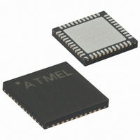
ATMEGA164P-20MU Atmel, ATMEGA164P-20MU Datasheet - Page 433

ATMEGA164P-20MU
Manufacturer Part Number
ATMEGA164P-20MU
Description
IC MCU AVR 16K FLASH 44-QFN
Manufacturer
Atmel
Series
AVR® ATmegar
Specifications of ATMEGA164P-20MU
Core Processor
AVR
Core Size
8-Bit
Speed
20MHz
Connectivity
I²C, SPI, UART/USART
Peripherals
Brown-out Detect/Reset, POR, PWM, WDT
Number Of I /o
32
Program Memory Size
16KB (8K x 16)
Program Memory Type
FLASH
Eeprom Size
512 x 8
Ram Size
1K x 8
Voltage - Supply (vcc/vdd)
2.7 V ~ 5.5 V
Data Converters
A/D 8x10b
Oscillator Type
Internal
Operating Temperature
-40°C ~ 85°C
Package / Case
44-VQFN Exposed Pad
Processor Series
ATMEGA16x
Core
AVR8
Data Bus Width
8 bit
Data Ram Size
1 KB
Interface Type
2-Wire/JTAG/SPI/USART
Maximum Clock Frequency
20 MHz
Number Of Programmable I/os
32
Number Of Timers
3
Maximum Operating Temperature
+ 85 C
Mounting Style
SMD/SMT
3rd Party Development Tools
EWAVR, EWAVR-BL
Development Tools By Supplier
ATAVRDRAGON, ATSTK500, ATSTK600, ATAVRISP2, ATAVRONEKIT
Minimum Operating Temperature
- 40 C
On-chip Adc
8-ch x 10-bit
Package
44MLF
Device Core
AVR
Family Name
ATmega
Maximum Speed
20 MHz
Operating Supply Voltage
3.3|5 V
For Use With
ATSTK600-TQFP44 - STK600 SOCKET/ADAPTER 44-TQFPATSTK600 - DEV KIT FOR AVR/AVR32770-1007 - ISP 4PORT ATMEL AVR MCU SPI/JTAGATAVRISP2 - PROGRAMMER AVR IN SYSTEM
Lead Free Status / RoHS Status
Lead free / RoHS Compliant
Available stocks
Company
Part Number
Manufacturer
Quantity
Price
Part Number:
ATMEGA164P-20MU
Manufacturer:
ATMEL/爱特梅尔
Quantity:
20 000
- Current page: 433 of 439
- Download datasheet (10Mb)
8011O–AVR–07/10
10 External Interrupts ................................................................................. 67
11 I/O-Ports .................................................................................................. 72
12 8-bit Timer/Counter0 with PWM ............................................................ 93
13 16-bit Timer/Counter1 with PWM ........................................................ 111
14 8-bit Timer/Counter2 with PWM and Asynchronous Operation ...... 139
10.1 Overview ..............................................................................................................67
10.2 Register Description .............................................................................................67
11.1 Overview ..............................................................................................................72
11.2 Ports as General Digital I/O ..................................................................................73
11.3 Alternate Port Functions .......................................................................................78
11.4 Register Description .............................................................................................91
12.1 Features ...............................................................................................................93
12.2 Overview ..............................................................................................................93
12.3 Timer/Counter Clock Sources ..............................................................................94
12.4 Counter Unit .........................................................................................................94
12.5 Output Compare Unit ...........................................................................................95
12.6 Compare Match Output Unit .................................................................................97
12.7 Modes of Operation ..............................................................................................98
12.8 Timer/Counter Timing Diagrams ........................................................................102
12.9 Register Description ...........................................................................................104
13.1 Features .............................................................................................................111
13.2 Overview ............................................................................................................111
13.3 Accessing 16-bit Registers .................................................................................113
13.4 Timer/Counter Clock Sources ............................................................................116
13.5 Counter Unit .......................................................................................................117
13.6 Input Capture Unit ..............................................................................................118
13.7 Output Compare Units ........................................................................................120
13.8 Compare Match Output Unit ...............................................................................122
13.9 Modes of Operation ............................................................................................123
13.10 Timer/Counter Timing Diagrams ......................................................................130
13.11 Register Description .........................................................................................132
14.1 Features .............................................................................................................139
14.2 Overview ............................................................................................................139
14.3 Timer/Counter Clock Sources ............................................................................140
14.4 Counter Unit .......................................................................................................141
ATmega164P/324P/644P
iii
Related parts for ATMEGA164P-20MU
Image
Part Number
Description
Manufacturer
Datasheet
Request
R

Part Number:
Description:
8-bit Microcontroller With 16/32/64k Bytes In-system Programmable Flash - Atmel Corporation
Manufacturer:
ATMEL Corporation
Datasheet:

Part Number:
Description:
8-bit Microcontroller with 16/32/64K Bytes In-System Programmable Flash
Manufacturer:
ATMEL [ATMEL Corporation]
Datasheet:

Part Number:
Description:
Manufacturer:
Atmel Corporation
Datasheet:

Part Number:
Description:
IC AVR MCU 16K 16MHZ 5V 44TQFP
Manufacturer:
Atmel
Datasheet:

Part Number:
Description:
IC AVR MCU 16K 16MHZ 5V 44-QFN
Manufacturer:
Atmel
Datasheet:

Part Number:
Description:
IC AVR MCU 16K 16MHZ 5V 40DIP
Manufacturer:
Atmel
Datasheet:

Part Number:
Description:
MCU AVR 16K FLASH 16MHZ 44-QFN
Manufacturer:
Atmel
Datasheet:

Part Number:
Description:
IC AVR MCU 16K 16MHZ COM 40-DIP
Manufacturer:
Atmel
Datasheet:

Part Number:
Description:
IC AVR MCU 16K 16MHZ COM 44-QFN
Manufacturer:
Atmel
Datasheet:

Part Number:
Description:
IC AVR MCU 16K 16MHZ IND 40-DIP
Manufacturer:
Atmel
Datasheet:

Part Number:
Description:
IC AVR MCU 16K 16MHZ IND 44-QFN
Manufacturer:
Atmel
Datasheet:

Part Number:
Description:
IC AVR MCU 16K 16MHZ IND 44-TQFP
Manufacturer:
Atmel
Datasheet:

Part Number:
Description:
IC MCU 8BIT 16KB FLASH 44TQFP
Manufacturer:
Atmel
Datasheet:

Part Number:
Description:
MCU AVR 16K FLASH 16MHZ 44-TQFP
Manufacturer:
Atmel
Datasheet:


