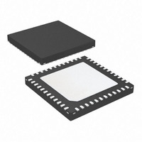
AT91SAM7S32B-MU Atmel, AT91SAM7S32B-MU Datasheet - Page 90

AT91SAM7S32B-MU
Manufacturer Part Number
AT91SAM7S32B-MU
Description
IC MCU ARM7 32KB FLASH 48-VQFN
Manufacturer
Atmel
Series
AT91SAMr
Datasheet
1.AT91SAM7S16-MU.pdf
(779 pages)
Specifications of AT91SAM7S32B-MU
Core Processor
ARM7
Core Size
16/32-Bit
Speed
55MHz
Connectivity
I²C, SPI, SSC, UART/USART
Peripherals
Brown-out Detect/Reset, DMA, POR, PWM, WDT
Number Of I /o
21
Program Memory Size
32KB (32K x 8)
Program Memory Type
FLASH
Ram Size
8K x 8
Voltage - Supply (vcc/vdd)
1.65 V ~ 1.95 V
Data Converters
A/D 8x10b
Oscillator Type
Internal
Operating Temperature
-40°C ~ 85°C
Package / Case
48-VQFN Exposed Pad, 48-HVQFN, 48-SQFN, 48-DHVQFN
For Use With
AT91SAM-ICE - EMULATOR FOR AT91 ARM7/ARM9AT91SAM7S-EK - KIT EVAL FOR ARM AT91SAM7S
Lead Free Status / RoHS Status
Lead free / RoHS Compliant
Eeprom Size
-
Available stocks
Company
Part Number
Manufacturer
Quantity
Price
- Current page: 90 of 779
- Download datasheet (11Mb)
16.3
Functional Description
The Watchdog Timer can be used to prevent system lock-up if the software becomes trapped in
a deadlock. It is supplied with VDDCORE. It restarts with initial values on processor reset.
The Watchdog is built around a 12-bit down counter, which is loaded with the value defined in
the field WDV of the Mode Register (WDT_MR). The Watchdog Timer uses the Slow Clock
divided by 128 to establish the maximum Watchdog period to be 16 seconds (with a typical Slow
Clock of 32.768 kHz).
After a Processor Reset, the value of WDV is 0xFFF, corresponding to the maximum value of
the counter with the external reset generation enabled (field WDRSTEN at 1 after a Backup
Reset). This means that a default Watchdog is running at reset, i.e., at power-up. The user must
either disable it (by setting the WDDIS bit in WDT_MR) if he does not expect to use it or must
reprogram it to meet the maximum Watchdog period the application requires.
The Watchdog Mode Register (WDT_MR) can be written only once. Only a processor reset
resets it. Writing the WDT_MR register reloads the timer with the newly programmed mode
parameters.
In normal operation, the user reloads the Watchdog at regular intervals before the timer under-
flow occurs, by writing the Control Register (WDT_CR) with the bit WDRSTT to 1. The
Watchdog counter is then immediately reloaded from WDT_MR and restarted, and the Slow
Clock 128 divider is reset and restarted. The WDT_CR register is write-protected. As a result,
writing WDT_CR without the correct hard-coded key has no effect. If an underflow does occur,
the “wdt_fault” signal to the Reset Controller is asserted if the bit WDRSTEN is set in the Mode
Register (WDT_MR). Moreover, the bit WDUNF is set in the Watchdog Status Register
(WDT_SR).
To prevent a software deadlock that continuously triggers the Watchdog, the reload of the
Watchdog must occur while the Watchdog counter is within a window between 0 and WDD,
WDD is defined in the WatchDog Mode Register WDT_MR.
Any attempt to restart the Watchdog while the Watchdog counter is between WDV and WDD
results in a Watchdog error, even if the Watchdog is disabled. The bit WDERR is updated in the
WDT_SR and the “wdt_fault” signal to the Reset Controller is asserted.
Note that this feature can be disabled by programming a WDD value greater than or equal to the
WDV value. In such a configuration, restarting the Watchdog Timer is permitted in the whole
range [0; WDV] and does not generate an error. This is the default configuration on reset (the
WDD and WDV values are equal).
The status bits WDUNF (Watchdog Underflow) and WDERR (Watchdog Error) trigger an inter-
rupt, provided the bit WDFIEN is set in the mode register. The signal “wdt_fault” to the reset
controller causes a Watchdog reset if the WDRSTEN bit is set as already explained in the reset
controller programmer Datasheet. In that case, the processor and the Watchdog Timer are
reset, and the WDERR and WDUNF flags are reset.
If a reset is generated or if WDT_SR is read, the status bits are reset, the interrupt is cleared,
and the “wdt_fault” signal to the reset controller is deasserted.
Writing the WDT_MR reloads and restarts the down counter.
While the processor is in debug state or in idle mode, the counter may be stopped depending on
the value programmed for the bits WDIDLEHLT and WDDBGHLT in the WDT_MR.
AT91SAM7S Series Preliminary
90
6175K–ATARM–30-Aug-10
Related parts for AT91SAM7S32B-MU
Image
Part Number
Description
Manufacturer
Datasheet
Request
R

Part Number:
Description:
KIT EVAL FOR ARM AT91SAM7S
Manufacturer:
Atmel
Datasheet:

Part Number:
Description:
MCU, MPU & DSP Development Tools KICKSTART KIT ATMEL AT91SAM7S
Manufacturer:
IAR Systems

Part Number:
Description:
DEV KIT FOR AVR/AVR32
Manufacturer:
Atmel
Datasheet:

Part Number:
Description:
INTERVAL AND WIPE/WASH WIPER CONTROL IC WITH DELAY
Manufacturer:
ATMEL Corporation
Datasheet:

Part Number:
Description:
Low-Voltage Voice-Switched IC for Hands-Free Operation
Manufacturer:
ATMEL Corporation
Datasheet:

Part Number:
Description:
MONOLITHIC INTEGRATED FEATUREPHONE CIRCUIT
Manufacturer:
ATMEL Corporation
Datasheet:

Part Number:
Description:
AM-FM Receiver IC U4255BM-M
Manufacturer:
ATMEL Corporation
Datasheet:

Part Number:
Description:
Monolithic Integrated Feature Phone Circuit
Manufacturer:
ATMEL Corporation
Datasheet:

Part Number:
Description:
Multistandard Video-IF and Quasi Parallel Sound Processing
Manufacturer:
ATMEL Corporation
Datasheet:

Part Number:
Description:
High-performance EE PLD
Manufacturer:
ATMEL Corporation
Datasheet:

Part Number:
Description:
8-bit Flash Microcontroller
Manufacturer:
ATMEL Corporation
Datasheet:

Part Number:
Description:
2-Wire Serial EEPROM
Manufacturer:
ATMEL Corporation
Datasheet:


