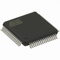
AT89C5122D-RDRUM Atmel, AT89C5122D-RDRUM Datasheet - Page 70

AT89C5122D-RDRUM
Manufacturer Part Number
AT89C5122D-RDRUM
Description
IC 8051 MCU 32K CRAM USB 64-VQFP
Manufacturer
Atmel
Series
89Cr
Datasheet
1.AT89C5122D-PSTUM.pdf
(208 pages)
Specifications of AT89C5122D-RDRUM
Core Processor
8051
Core Size
8-Bit
Speed
48MHz
Connectivity
SmartCard, SPI, UART/USART, USB
Peripherals
LED, POR, WDT
Number Of I /o
46
Program Memory Size
32KB (32K x 8)
Program Memory Type
FLASH
Ram Size
768 x 8
Voltage - Supply (vcc/vdd)
3 V ~ 5.5 V
Oscillator Type
Internal
Operating Temperature
-40°C ~ 85°C
Package / Case
64-TQFP, 64-VQFP
For Use With
AT89OCD-01 - USB EMULATOR FOR AT8XC51 MCUAT89STK-10 - KIT EVAL APPL MASS STORAGEAT89STK-03 - KIT STARTER FOR MCU AT8XC5122/23
Lead Free Status / RoHS Status
Lead free / RoHS Compliant
Eeprom Size
-
Data Converters
-
Other names
AT89C5122D-RDRUMTR
Available stocks
Company
Part Number
Manufacturer
Quantity
Price
- Current page: 70 of 208
- Download datasheet (3Mb)
Power-on and Power-off FSM
70
AT83R5122, AT8xC5122/23
The Power-on Power-off Finite State Machine (FSM) applies the signals on the smart
card in accordance with ISO7816-3 standard. It conducts the Activation (Cold Reset and
Warm Reset as well as De-Activation) it also manages the exception conditions such as
overcurrent (see DC/DC Converter)
To be able to power on the SCIB, the card presence is mandatory. Upon detectection of
a card presence, the Terminal initiate a Cold Reset Activation.
The Cold Reset Activation Terminal procedure is as follow and the Figure 36. Timing
indications are given according to ISO IEC 7816
Figure 36. SCIB Activation Cold Reset Sequence after a Card Insertion
The Warm Reset Activation Terminal procedure is as follow and the Figure 37
Figure 37. SCIB Activation Warm Reset Sequence
–
–
–
–
–
–
–
–
–
–
CCLK
CCLK
CRST
CRST
CIO
CIO
CVCC
CVCC
RESET= Low , I/O in the receive state
Power Vcc (see DC/DC Converter)
Once Vcc is established, apply Clock at time Ta
Maintain Reset Low until time Ta+tb (tb< 400 clocks)
Monitor The I/O line for the Answer To Reset (ATR) between 400 and 40000
clock cycles after Tb. ( 400 clocks < tc < 40000clocks)
Vcc active, Reset = High, CLK active
Terminal drive Reset low at time T to initiate the warm Reset. Reset=0
maintained for at least 400 clocks until time Td = T+te (400 clocks < te)
Terminal keep the IO line in receive state
Terminal drive Reset high after at least 400 clocks at time Td
ICC shall respond with an ATR within 40000 clocks (tf<40000 clocks)
Undefined
Undefined
Ta
T
Ta+tb
Td=T + te
Tb+tc
Td + tf
Data
Data
4202F–SCR–07/2008
Related parts for AT89C5122D-RDRUM
Image
Part Number
Description
Manufacturer
Datasheet
Request
R

Part Number:
Description:
IC 8051 MCU W/SMART CARD 64VQFP
Manufacturer:
Atmel
Datasheet:

Part Number:
Description:
IC 8051 MCU FLASH 32K 64QFN
Manufacturer:
Atmel
Datasheet:

Part Number:
Description:
IC 8051 MCU FLASH 32K 64VQFP
Manufacturer:
Atmel
Datasheet:

Part Number:
Description:
IC MCU 80C51 W/SMART CARD 64VQFP
Manufacturer:
Atmel
Datasheet:

Part Number:
Description:
IC 8051 MCU FLASH 32K 28PLCC
Manufacturer:
Atmel
Datasheet:

Part Number:
Description:
MICROCONTROLLER WITH USB AND SMART CARD READER INTERFACES
Manufacturer:
ATMEL [ATMEL Corporation]
Datasheet:

Part Number:
Description:
KIT STARTER FOR MCU AT8XC5122/23
Manufacturer:
Atmel
Datasheet:

Part Number:
Description:
IC MICRO CTRL 24MHZ 44TQFP
Manufacturer:
Atmel
Datasheet:

Part Number:
Description:
IC MICRO CTRL 24MHZ 44PLCC
Manufacturer:
Atmel
Datasheet:

Part Number:
Description:
IC MICRO CTRL 24MHZ 44PLCC
Manufacturer:
Atmel
Datasheet:

Part Number:
Description:
IC MICRO CTRL 24MHZ 40DIP
Manufacturer:
Atmel
Datasheet:


