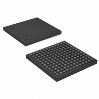
AT91SAM7L128-CU Atmel, AT91SAM7L128-CU Datasheet - Page 117

AT91SAM7L128-CU
Manufacturer Part Number
AT91SAM7L128-CU
Description
MCU ARM7 128K HS FLASH 144-LFBGA
Manufacturer
Atmel
Series
AT91SAMr
Datasheet
1.AT91SAM7L64-CU.pdf
(564 pages)
Specifications of AT91SAM7L128-CU
Core Processor
ARM7
Core Size
16/32-Bit
Speed
36MHz
Connectivity
I²C, SPI, UART/USART
Peripherals
Brown-out Detect/Reset, LCD, POR, PWM, WDT
Number Of I /o
80
Program Memory Size
128KB (128K x 8)
Program Memory Type
FLASH
Ram Size
6K x 8
Voltage - Supply (vcc/vdd)
1.55 V ~ 1.8 V
Data Converters
A/D 4x10b
Oscillator Type
Internal
Operating Temperature
-40°C ~ 85°C
Package / Case
144-LFBGA
Processor Series
AT91SAMx
Core
ARM7TDMI
Data Bus Width
32 bit
Data Ram Size
6 KB
Interface Type
2-Wire, SPI, USART
Maximum Clock Frequency
36 MHz
Number Of Programmable I/os
80
Number Of Timers
3
Maximum Operating Temperature
+ 85 C
Mounting Style
SMD/SMT
3rd Party Development Tools
JTRACE-ARM-2M, MDK-ARM, RL-ARM, ULINK2
Development Tools By Supplier
AT91SAM-ICE, AT91-ISP, AT91SAM7L-EK
Minimum Operating Temperature
- 40 C
On-chip Adc
10 bit, 4 Channel
For Use With
AT91SAM7L-STK - KIT EVAL FOR AT91SAM7LAT91SAM-ICE - EMULATOR FOR AT91 ARM7/ARM9
Lead Free Status / RoHS Status
Lead free / RoHS Compliant
Eeprom Size
-
Lead Free Status / Rohs Status
Details
Available stocks
Company
Part Number
Manufacturer
Quantity
Price
Company:
Part Number:
AT91SAM7L128-CU
Manufacturer:
Atmel
Quantity:
2 660
- Current page: 117 of 564
- Download datasheet (9Mb)
17.3.7.3
17.3.7.4
6257A–ATARM–20-Feb-08
Clock Alarms
Brownout Detector
All the resulting signals are wired-ORed to trigger a debounce counter, which can be pro-
grammed with the WKUPDBC field in the Supply Controller Wake Up Mode Register,
SUPC_WUMR. The WKUPDBC field can select a debouncing period of 3, 32, 512, 4,096 or
32,768 slow clock cycles. This corresponds respectively to about 100 µs, about 1 ms, about
16 ms, about 128 ms and about 1 second (for a typical slow clock frequency of 32 kHz). Pro-
gramming WKUPDBC to 0x0 selects an immediate wake up, i.e., an enabled WKUP pin must be
active according to its polarity during a minimum of one slow clock period to wake up the core
power supply.
If an enabled WKUP pin is asserted for a time longer than the debouncing period, a wake up of
the core power supply is started and the signals, WKUP0 to WKUP15 as shown in
are latched in the Supply Controller Status Register, SUPC_SR. This allows the user to identify
the source of the wake up, however, if a new wake up condition occurs, the primary information
is lost. No new wake up can be detected since the primary wake up condition has disappeared.
The RTC alarm can generate a wake up of the core power supply. This can be enabled by writ-
ing, the bit RTCEN to 1 in the Supply Controller Wake Up Mode Register, SUPC_WUMR.
The Supply Controller does not provide any status as the information is available in the User
Interface of the Real Time Clock.
The brownout detector can generate a wake up of the core power supply. This can be enabled
by writing the BODEN bit to 1 in the Supply Controller Mode Register, SUPC_MR.
The Supply Controller provides two status bits in the Supply Controller Status Register for the
brownout detector which allow to determine whether the last wake up was due to the brownout
detector:
• the BROWNOUT bit provides real time information, which is updated at each measurement
• the BODS bit provides saved information and shows a brownout has occurred since the last
cycle or updated at each Slow Clock cycle, if the measurement is continuous
read of SUPC_SR
AT91SAM7L128/64 Preliminary
Figure
17-8,
117
Related parts for AT91SAM7L128-CU
Image
Part Number
Description
Manufacturer
Datasheet
Request
R

Part Number:
Description:
KIT EVAL FOR AT91SAM7L
Manufacturer:
Atmel
Datasheet:

Part Number:
Description:
DEV KIT FOR AVR/AVR32
Manufacturer:
Atmel
Datasheet:

Part Number:
Description:
INTERVAL AND WIPE/WASH WIPER CONTROL IC WITH DELAY
Manufacturer:
ATMEL Corporation
Datasheet:

Part Number:
Description:
Low-Voltage Voice-Switched IC for Hands-Free Operation
Manufacturer:
ATMEL Corporation
Datasheet:

Part Number:
Description:
MONOLITHIC INTEGRATED FEATUREPHONE CIRCUIT
Manufacturer:
ATMEL Corporation
Datasheet:

Part Number:
Description:
AM-FM Receiver IC U4255BM-M
Manufacturer:
ATMEL Corporation
Datasheet:

Part Number:
Description:
Monolithic Integrated Feature Phone Circuit
Manufacturer:
ATMEL Corporation
Datasheet:

Part Number:
Description:
Multistandard Video-IF and Quasi Parallel Sound Processing
Manufacturer:
ATMEL Corporation
Datasheet:

Part Number:
Description:
High-performance EE PLD
Manufacturer:
ATMEL Corporation
Datasheet:

Part Number:
Description:
8-bit Flash Microcontroller
Manufacturer:
ATMEL Corporation
Datasheet:

Part Number:
Description:
2-Wire Serial EEPROM
Manufacturer:
ATMEL Corporation
Datasheet:


