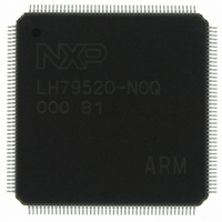
LH79520N0Q000B1;55 NXP Semiconductors, LH79520N0Q000B1;55 Datasheet - Page 49

LH79520N0Q000B1;55
Manufacturer Part Number
LH79520N0Q000B1;55
Description
IC ARM7 BLUESTREAK MCU 176LQFP
Manufacturer
NXP Semiconductors
Series
BlueStreak ; LH7r
Datasheet
1.LH79520N0Q000B155.pdf
(59 pages)
Specifications of LH79520N0Q000B1;55
Package / Case
176-LQFP
Core Processor
ARM7
Core Size
32-Bit
Speed
77.4MHz
Connectivity
EBI/EMI, IrDA, Microwire, SPI, SSI, SSP, UART/USART
Peripherals
DMA, LCD, POR, PWM, WDT
Number Of I /o
64
Program Memory Type
ROMless
Ram Size
32K x 8
Voltage - Supply (vcc/vdd)
1.62 V ~ 3.6 V
Oscillator Type
External
Operating Temperature
-40°C ~ 85°C
Processor Series
LH795
Core
ARM7TDMI-S
Data Bus Width
32 bit
Data Ram Size
32 KB
Interface Type
JTAG, UART
Maximum Clock Frequency
77.4 MHz
Number Of Programmable I/os
64
Number Of Timers
3
Operating Supply Voltage
1.8 V
Maximum Operating Temperature
+ 85 C
Mounting Style
SMD/SMT
3rd Party Development Tools
MDK-ARM, RL-ARM, ULINK2
Minimum Operating Temperature
- 40 C
Lead Free Status / RoHS Status
Lead free / RoHS Compliant
Eeprom Size
-
Program Memory Size
-
Data Converters
-
Lead Free Status / Rohs Status
Lead free / RoHS Compliant
Other names
568-4331
935285044557
LH79520N0Q000B1
935285044557
LH79520N0Q000B1
System-on-Chip
Power Supply Sequencing
the 3.3 V supply. Otherwise, the 1.8 V supply may not
lag the 3.3 V supply by more than 10
ence between the two power supplies must be within
1.5 V during power supply ramp up.
should only be applied to input pins after the device is
powered-up as described above.
Low Operating Temperatures and
Noise Immunity
perature of the transistors in the integrated circuit. The
switching speed of the CMOS circuitry within the SoC
depends partly on Tj, and the lower the operating tem-
perature, the faster the CMOS circuits will switch.
Increased switching noise generated by faster switch-
ing circuits could affect the overall system stability. The
amount of switching noise is directly affected by the
application executed on the SoC.
Preliminary data sheet
The 1.8 V power supply must be energized before
If a longer delay time is needed, the voltage differ-
To prevent a potential latch-up condition, voltage
The junction temperature, Tj, is the operating tem-
Figure 31. TAP Controller Reset Circuit Example
nRESETIN
nTRST
µs
.
Rev. 01 — 16 July 2007
NXP Semiconductors
to meet industrial temperature standards should use an
external oscillator rather than a crystal to drive the sys-
tem clock input of the System-on-Chip. This change
from crystal to oscillator will increase the robustness
(i.e., noise immunity of the clock input to the SoC).
Assuring Proper Reset Behavior
on was designed into the LH79520 to give the Designer
control over how the chip boots up and to be useful for
bringing up software and hardware using E-ICE.
initial reset pulse is required for the TAP controller
when Power-on Reset is asserted.
TAP controller reset. This is a recommendation;
Designers should assess their requirements and imple-
ment a solution that satisfies them.
gate to AND the nRESETIN and nTRST signals, insur-
ing that the TAP Controller gets reset with either signal,
and the LH79520 always powers up in Normal Mode.
nTRST
nRESETIN
NXP recommends that users implementing a system
A separate reset for the TAP controller and power-
However, for the LH79520 to enter Normal mode, an
Figure 31 illustrates one method for assuring proper
This recommended circuit uses an external AND
LH79520
79520-174
LH79520
49


