MC908AP32CBE Freescale Semiconductor, MC908AP32CBE Datasheet - Page 259
MC908AP32CBE
Manufacturer Part Number
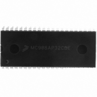
MC908AP32CBE
Description
IC MCU 32K FLASH 8MHZ 42DIP
Manufacturer
Freescale Semiconductor
Series
HC08r
Specifications of MC908AP32CBE
Core Processor
HC08
Core Size
8-Bit
Speed
8MHz
Connectivity
I²C, IRSCI, SCI, SPI
Peripherals
LED, LVD, POR, PWM
Number Of I /o
30
Program Memory Size
32KB (32K x 8)
Program Memory Type
FLASH
Ram Size
2K x 8
Voltage - Supply (vcc/vdd)
2.7 V ~ 5.5 V
Data Converters
A/D 8x10b
Oscillator Type
Internal
Operating Temperature
-40°C ~ 85°C
Package / Case
42-DIP (0.600", 15.24mm)
Controller Family/series
HC08
No. Of I/o's
30
Ram Memory Size
2KB
Cpu Speed
8MHz
No. Of Timers
2
Embedded Interface Type
I2C, SCI, SPI
Rohs Compliant
Yes
Processor Series
HC08AP
Core
HC08
Data Bus Width
8 bit
Data Ram Size
2 KB
Interface Type
SCI, SPI
Maximum Clock Frequency
8 MHz
Number Of Programmable I/os
32
Number Of Timers
4
Maximum Operating Temperature
+ 85 C
Mounting Style
Through Hole
Development Tools By Supplier
FSICEBASE, DEMO908AP64E, M68CBL05CE
Minimum Operating Temperature
- 40 C
On-chip Adc
10 bit, 8 Channel
Lead Free Status / RoHS Status
Lead free / RoHS Compliant
Eeprom Size
-
Lead Free Status / Rohs Status
Details


15.7.4 ADC Auto-Scan Mode Data Registers (ADRL1–ADRL3)
The ADC data registers 1 to 3 (ADRL1–ADRL3), are 8-bit registers for conversion results in 8-bit
truncated mode, for channels ADC1 to ADC3, when the ADC is operating in auto-scan mode
(MODE[1:0] = 00).
15.7.5 ADC Auto-Scan Control Register (ADASCR)
The ADC auto-scan control register (ADASCR) enables and controls the ADC auto-scan function.
AUTO[1:0] — Auto-Scan Mode Channel Select Bits
Freescale Semiconductor
$0059
$005A
Addr.
AUTO1 and AUTO0 form a 2-bit field which is used to define the number of auto-scan channels used
when in auto-scan mode. Reset clears these bits.
ADC Data Register High 0
ADC Data Register Low 0
Register Name
Address: ADRL1, $005B; ADRL2, $005C; and ADRL3, $005D
Address:
Reset:
Reset:
Read:
Read:
Write:
Write:
Figure 15-8 ADRH0 and ADRL0 in Left Justified Sign Data Mode
Figure 15-9. ADC Data Register Low 1 to 3 (ADRL1–ADRL3)
(ADRH0)
(ADRL0)
$005E
AD9
Figure 15-10. ADC Scan Control Register (ADASCR)
R
R
0
0
0
Reset:
Reset:
Read:
Read:
Write:
Write:
AUTO1
Table 15-4. Auto-scan Mode Channel Select
= Reserved
= Unimplemented
0
0
1
1
AD8
R
0
0
0
MC68HC908AP Family Data Sheet, Rev. 4
Bit 7
AD9
AD1
R
R
0
0
AUTO0
AD7
0
1
0
1
R
0
0
0
AD8
AD0
R
R
6
0
0
ADC0 only
ADC0 to ADC1
ADC0 to ADC2
ADC0 to ADC3
AD6
R
0
0
0
AD7
Auto-Scan Channels
R
R
5
0
0
0
AD5
R
R
0
0
0
AD6
R
R
4
0
0
0
= Reserved
AUTO1
AD4
R
0
0
AD5
R
R
3
0
0
0
AUTO0
AD3
R
0
0
AD4
R
R
2
0
0
0
ASCAN
AD2
R
0
0
AD3
R
R
1
0
0
0
I/O Registers
Bit 0
AD2
R
R
0
0
0
257
Related parts for MC908AP32CBE
Image
Part Number
Description
Manufacturer
Datasheet
Request
R

Part Number:
Description:
Manufacturer:
Freescale Semiconductor, Inc
Datasheet:
Part Number:
Description:
Manufacturer:
Freescale Semiconductor, Inc
Datasheet:
Part Number:
Description:
Manufacturer:
Freescale Semiconductor, Inc
Datasheet:
Part Number:
Description:
Manufacturer:
Freescale Semiconductor, Inc
Datasheet:
Part Number:
Description:
Manufacturer:
Freescale Semiconductor, Inc
Datasheet:
Part Number:
Description:
Manufacturer:
Freescale Semiconductor, Inc
Datasheet:
Part Number:
Description:
Manufacturer:
Freescale Semiconductor, Inc
Datasheet:
Part Number:
Description:
Manufacturer:
Freescale Semiconductor, Inc
Datasheet:
Part Number:
Description:
Manufacturer:
Freescale Semiconductor, Inc
Datasheet:
Part Number:
Description:
Manufacturer:
Freescale Semiconductor, Inc
Datasheet:
Part Number:
Description:
Manufacturer:
Freescale Semiconductor, Inc
Datasheet:
Part Number:
Description:
Manufacturer:
Freescale Semiconductor, Inc
Datasheet:
Part Number:
Description:
Manufacturer:
Freescale Semiconductor, Inc
Datasheet:
Part Number:
Description:
Manufacturer:
Freescale Semiconductor, Inc
Datasheet:
Part Number:
Description:
Manufacturer:
Freescale Semiconductor, Inc
Datasheet: