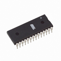
AT89LP828-20PU Atmel, AT89LP828-20PU Datasheet - Page 68

AT89LP828-20PU
Manufacturer Part Number
AT89LP828-20PU
Description
MCU 8051 8K FLASH SPI 28PDIP
Manufacturer
Atmel
Series
89LPr
Datasheet
1.AT89LP428-20AU.pdf
(149 pages)
Specifications of AT89LP828-20PU
Core Processor
8051
Core Size
8-Bit
Speed
20MHz
Connectivity
SPI, UART/USART
Peripherals
Brown-out Detect/Reset, POR, PWM, WDT
Number Of I /o
30
Program Memory Size
8KB (8K x 8)
Program Memory Type
FLASH
Eeprom Size
1K x 8
Ram Size
768 x 8
Voltage - Supply (vcc/vdd)
2.4 V ~ 5.5 V
Oscillator Type
Internal
Operating Temperature
-40°C ~ 85°C
Package / Case
28-DIP (0.300", 7.62mm)
Processor Series
AT89x
Core
8051
Data Bus Width
8 bit
Data Ram Size
768 B
Interface Type
2-Wire, SPI
Maximum Clock Frequency
20 MHz
Number Of Programmable I/os
30
Number Of Timers
3
Maximum Operating Temperature
+ 85 C
Mounting Style
Through Hole
3rd Party Development Tools
PK51, CA51, A51, ULINK2
Development Tools By Supplier
AT89ISP
Minimum Operating Temperature
- 40 C
Lead Free Status / RoHS Status
Lead free / RoHS Compliant
Data Converters
-
Lead Free Status / Rohs Status
Details
Available stocks
Company
Part Number
Manufacturer
Quantity
Price
Company:
Part Number:
AT89LP828-20PU
Manufacturer:
NXP
Quantity:
3 942
13.3.1.3
13.3.2
13.4
68
Pulse Width Modulation Mode
AT89LP428/828
Timer 2 Operation for Compare Mode
Dual-Slope Mode
Figure 13-5. CTC Mode Waveform Example
The dual-slope mode occurs when CP/RL2 = 0 and T2CM
of the output is determined by the TOP value stored in RCAP2L and RCAP2H and output edges
occur at fractions of the timer period on both the up and down count.
example of outputting two symmetrical waveforms using the toggle on match action. More com-
plex waveforms are achieved by changing the TOP value and the compare values more
frequently.
Figure 13-6. Dual-slope Waveform Example
Compare channels will work with any Timer 2 operating mode. The full 16-bit compare range
may not be available in all modes. In order for a compare output action to take place, the com-
pare values must be within the counting range of Timer 2. CTCx must be cleared to 0 for all
channels if Timer 2 is operating in Baud Rate mode or errors may occur in the serial
communication.
In Pulse Width Modulation (PWM) mode, a compare channel can output a square wave with pro-
grammable frequency and duty cycle. Setting CCMx = 1 and CxM
mode. PWM mode is similar to Output Compare mode except that the compare value is double-
buffered. A diagram of a CCA channel in PWM mode is shown in
is selectable between inverting and non-inverting modes. PWM is intended for use with Timer 2
in Auto-reload mode (CP/RL2 = 0, DCEN = 0) using count modes 1, 2 or 3. The PWM can oper-
ate in asymmetric (edge-aligned) or symmetric (center-aligned) mode depending on the T2CM
selection. The CCA PWM has variable precision from 2 to 16 bits. A trade-off between frequency
{RCAP2H,RCA2L}
{CCAH,CCAL}
{CCAH,CCAL}
{CCBH,CCBL}
CCA
CCA
CCB
CP/RL2 = 0, T2CM
CP/RL2 = 1
1-0
1-0
= 10B, DCEN = 0
= 1xB. In this mode the frequency
Figure
2-0
13-7. The PWM polarity
Figure 13-6
= 10xB enables PWM
3654A–MICRO–8/09
shows an


