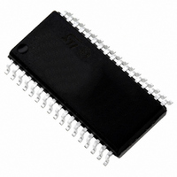
ST72F63BK2M1 STMicroelectronics, ST72F63BK2M1 Datasheet - Page 29

ST72F63BK2M1
Manufacturer Part Number
ST72F63BK2M1
Description
IC MCU 8BIT 8K FLASH 34-SOIC
Manufacturer
STMicroelectronics
Series
ST7r
Datasheet
1.ST72F63BD6U1TR.pdf
(186 pages)
Specifications of ST72F63BK2M1
Core Processor
ST7
Core Size
8-Bit
Speed
8MHz
Connectivity
I²C, SCI, USB
Peripherals
DMA, LVD, POR, PWM, WDT
Number Of I /o
19
Program Memory Size
8KB (8K x 8)
Program Memory Type
FLASH
Ram Size
384 x 8
Voltage - Supply (vcc/vdd)
4 V ~ 5.5 V
Data Converters
A/D 12x8b
Oscillator Type
External
Operating Temperature
0°C ~ 70°C
Package / Case
34-SOIC (7.5mm Width)
Processor Series
ST72F6x
Core
ST7
Data Bus Width
8 bit
Data Ram Size
384 B
Interface Type
I2C, SCI
Maximum Clock Frequency
8 MHz
Number Of Programmable I/os
27
Number Of Timers
2 x 16 bit
Operating Supply Voltage
4 V to 5.5 V
Maximum Operating Temperature
+ 70 C
Mounting Style
SMD/SMT
Development Tools By Supplier
ST7MDTU3-EPB/US, ST72F63B-SK/RAIS, ST7MDTU3-EMU3, STX-RLINK
Minimum Operating Temperature
0 C
On-chip Adc
8 bit
For Use With
497-5521 - EVAL BOARD LOW SPEED USB
Lead Free Status / RoHS Status
Lead free / RoHS Compliant
Eeprom Size
-
Lead Free Status / Rohs Status
Details
Available stocks
Company
Part Number
Manufacturer
Quantity
Price
Part Number:
ST72F63BK2M1
Manufacturer:
ST
Quantity:
20 000
ST7263Bxx
Condition Code register (CC)
Reset value: 111x1xxx
The 8-bit Condition Code register contains the interrupt mask and four flags representative
of the result of the instruction just executed. This register can also be handled by the PUSH
and POP instructions.
These bits can be individually tested and/or controlled by specific instructions.
7
1
Bit 4 H Half carry
Bit 3 I Interrupt mask
6
1
This bit is set by hardware when a carry occurs between bits 3 and 4 of the ALU
during an ADD or ADC instruction. It is reset by hardware during the same
instructions.
0: No half carry has occurred.
1: A half carry has occurred.
This bit is tested using the JRH or JRNH instruction. The H bit is useful in BCD
arithmetic subroutines.
This bit is set by hardware when entering in interrupt or by software to disable all
interrupts except the TRAP software interrupt. This bit is cleared by software.
0: Interrupts are enabled.
1: Interrupts are disabled.
This bit is controlled by the RIM, SIM and IRET instructions and is tested by the
JRM and JRNM instructions.
Note: Interrupts requested while I is set are latched and can be processed when I
is cleared. By default an interrupt routine is not interruptible because the I bit
is set by hardware at the start of the routine and reset by the IRET
instruction at the end of the routine. If the I bit is cleared by software in the
interrupt routine, pending interrupts are serviced regardless of the priority
level of the current interrupt routine.
5
1
Doc ID 7516 Rev 8
H
4
Read/write
3
I
N
2
Central processing unit
1
Z
C
0
29/186


