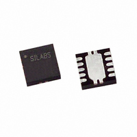
C8051F305-GMR Silicon Laboratories Inc, C8051F305-GMR Datasheet - Page 3

C8051F305-GMR
Manufacturer Part Number
C8051F305-GMR
Description
IC 8051 MCU 2K FLASH 11QFN
Manufacturer
Silicon Laboratories Inc
Series
C8051F30xr
Specifications of C8051F305-GMR
Core Processor
8051
Core Size
8-Bit
Speed
25MHz
Connectivity
SMBus (2-Wire/I²C), UART/USART
Peripherals
POR, PWM, WDT
Number Of I /o
8
Program Memory Size
2KB (2K x 8)
Program Memory Type
FLASH
Ram Size
256 x 8
Voltage - Supply (vcc/vdd)
2.7 V ~ 3.6 V
Oscillator Type
External
Operating Temperature
-40°C ~ 85°C
Package / Case
11-VQFN
For Use With
336-1444 - ADAPTER PROGRAM TOOLSTICK F300
Lead Free Status / RoHS Status
Lead free / RoHS Compliant
Eeprom Size
-
Data Converters
-
Available stocks
Company
Part Number
Manufacturer
Quantity
Price
Part Number:
C8051F305-GMR
Manufacturer:
SILICONLABS/芯科
Quantity:
20 000
Table of Contents
1. System Overview.................................................................................................... 13
2. Absolute Maximum Ratings .................................................................................. 24
3. Global Electrical Characteristics .......................................................................... 25
4. Pinout and Package Definitions............................................................................ 27
5. ADC0 (8-Bit ADC, C8051F300/2)............................................................................ 35
6. Voltage Reference (C8051F300/2) ......................................................................... 49
7. Comparator0 ........................................................................................................... 51
8. CIP-51 Microcontroller ........................................................................................... 57
1.1. CIP-51™ Microcontroller Core.......................................................................... 16
1.2. On-Chip Memory............................................................................................... 18
1.3. On-Chip Debug Circuitry................................................................................... 19
1.4. Programmable Digital I/O and Crossbar ........................................................... 19
1.5. Serial Ports ....................................................................................................... 20
1.6. Programmable Counter Array ........................................................................... 21
1.7. 8-Bit Analog to Digital Converter (C8051F300/2 Only) ..................................... 22
1.8. Comparator ....................................................................................................... 23
5.1. Analog Multiplexer and PGA............................................................................. 36
5.2. Temperature Sensor ......................................................................................... 36
5.3. Modes of Operation .......................................................................................... 39
5.4. Programmable Window Detector ...................................................................... 45
8.1. Instruction Set ................................................................................................... 58
8.2. Memory Organization........................................................................................ 63
8.3. Interrupt Handler ............................................................................................... 72
1.1.1. Fully 8051 Compatible.............................................................................. 16
1.1.2. Improved Throughput ............................................................................... 16
1.1.3. Additional Features .................................................................................. 17
5.3.1. Starting a Conversion............................................................................... 39
5.3.2. Tracking Modes........................................................................................ 40
5.3.3. Settling Time Requirements ..................................................................... 41
5.4.1. Window Detector In Single-Ended Mode ................................................. 45
5.4.2. Window Detector In Differential Mode...................................................... 46
8.1.1. Instruction and CPU Timing ..................................................................... 58
8.1.2. MOVX Instruction and Program Memory ................................................. 59
8.2.1. Program Memory...................................................................................... 63
8.2.2. Data Memory............................................................................................ 64
8.2.3. General Purpose Registers ...................................................................... 64
8.2.4. Bit Addressable Locations........................................................................ 65
8.2.5. Stack ....................................................................................................... 65
8.2.6. Special Function Registers....................................................................... 65
8.2.7. Register Descriptions ............................................................................... 68
8.3.1. MCU Interrupt Sources and Vectors ........................................................ 72
8.3.2. External Interrupts .................................................................................... 73
8.3.3. Interrupt Priorities ..................................................................................... 73
Rev. 2.9
C8051F300/1/2/3/4/5
3


