M38227ECFP Renesas Electronics America, M38227ECFP Datasheet - Page 14
M38227ECFP
Manufacturer Part Number
M38227ECFP
Description
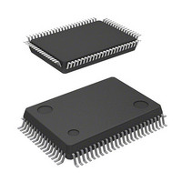
IC 740 MCU EPROM 48K 80QFP
Manufacturer
Renesas Electronics America
Series
740/38000r
Datasheet
1.M38227ECFP.pdf
(82 pages)
Specifications of M38227ECFP
Core Processor
740
Core Size
8-Bit
Speed
8MHz
Connectivity
SIO, UART/USART
Peripherals
LCD
Number Of I /o
49
Program Memory Size
48KB (48K x 8)
Program Memory Type
OTP
Ram Size
1K x 8
Voltage - Supply (vcc/vdd)
2.5 V ~ 5.5 V
Data Converters
A/D 8x8b
Oscillator Type
Internal
Operating Temperature
-20°C ~ 85°C
Package / Case
80-QFP
Lead Free Status / RoHS Status
Contains lead / RoHS non-compliant
Eeprom Size
-
Available stocks
Company
Part Number
Manufacturer
Quantity
Price
Company:

Part Number:
M38227ECFP
Manufacturer:
Renesas Electronics America
Quantity:
10 000
Part Number:
M38227ECFP
Manufacturer:
MIT
Quantity:
20 000
Company:
Part Number:
M38227ECFP#U0
Manufacturer:
Renesas Electronics America
Quantity:
10 000
Part Number:
M38227ECFP#U0
Manufacturer:
RENESAS/瑞萨
Quantity:
20 000


FUNCTIONAL DESCRIPTION
CENTRAL PROCESSING UNIT (CPU)
The 3822 group uses the standard 740 family instruction set. Re-
fer to the table of 740 family addressing modes and machine
instructions or the 740 Family Software Manual for details on the
instruction set.
Machine-resident 740 family instructions are as follows:
The FST and SLW instruction cannot be used.
The STP, WIT, MUL, and DIV instruction can be used.
[Accumulator (A)]
The accumulator is an 8-bit register. Data operations such as data
transfer, etc., are executed mainly through the accumulator.
[Index Register X (X)]
The index register X is an 8-bit register. In the index addressing
modes, the value of the OPERAND is added to the contents of
register X and specifies the real address.
[Index Register Y (Y)]
The index register Y is an 8-bit register. In partial instruction, the
value of the OPERAND is added to the contents of register Y and
specifies the real address.
Fig.9 740 Family CPU register structure
b15
PC
H
b7
b7
b7
b7
b7
b7
N V T B D I Z C
PC
A
X
Y
S
L
[Stack Pointer (S)]
The stack pointer is an 8-bit register used during subroutine calls
and interrupts. This register indicates start address of stored area
(stack) for storing registers during subroutine calls and interrupts.
The low-order 8 bits of the stack address are determined by the
contents of the stack pointer. The high-order 8 bits of the stack ad-
dress are determined by the stack page selection bit. If the stack
page selection bit is “0” , the high-order 8 bits becomes “00
the stack page selection bit is “1”, the high-order 8 bits becomes
“01
The operations of pushing register contents onto the stack and
popping them from the stack are shown in Figure 10.
Store registers other than those described in Figure 10 with pro-
gram when the user needs them during interrupts or subroutine
calls.
[Program Counter (PC)]
The program counter is a 16-bit counter consisting of two 8-bit
registers PC
next instruction to be executed.
b0
b0
b0
b0
b0
b0
16
”.
Accumulator
Index register X
Index register Y
Stack pointer
Program counter
Processor status register (PS)
Carry flag
Zero flag
Interrupt disable flag
Decimal mode flag
Break flag
Index X mode flag
Overflow flag
Negative flag
SINGLE-CHIP 8-BIT CMOS MICROCOMPUTER
H
and PC
MITSUBISHI MICROCOMPUTERS
L
. It is used to indicate the address of the
3822 Group
16
”. If
11
Related parts for M38227ECFP
Image
Part Number
Description
Manufacturer
Datasheet
Request
R

Part Number:
Description:
KIT STARTER FOR M16C/29
Manufacturer:
Renesas Electronics America
Datasheet:

Part Number:
Description:
KIT STARTER FOR R8C/2D
Manufacturer:
Renesas Electronics America
Datasheet:

Part Number:
Description:
R0K33062P STARTER KIT
Manufacturer:
Renesas Electronics America
Datasheet:

Part Number:
Description:
KIT STARTER FOR R8C/23 E8A
Manufacturer:
Renesas Electronics America
Datasheet:

Part Number:
Description:
KIT STARTER FOR R8C/25
Manufacturer:
Renesas Electronics America
Datasheet:

Part Number:
Description:
KIT STARTER H8S2456 SHARPE DSPLY
Manufacturer:
Renesas Electronics America
Datasheet:

Part Number:
Description:
KIT STARTER FOR R8C38C
Manufacturer:
Renesas Electronics America
Datasheet:

Part Number:
Description:
KIT STARTER FOR R8C35C
Manufacturer:
Renesas Electronics America
Datasheet:

Part Number:
Description:
KIT STARTER FOR R8CL3AC+LCD APPS
Manufacturer:
Renesas Electronics America
Datasheet:
Part Number:
Description:
KIT STARTER FOR RX610
Manufacturer:
Renesas Electronics America
Datasheet:

Part Number:
Description:
KIT STARTER FOR R32C/118
Manufacturer:
Renesas Electronics America
Datasheet:

Part Number:
Description:
KIT DEV RSK-R8C/26-29
Manufacturer:
Renesas Electronics America
Datasheet:

Part Number:
Description:
KIT STARTER FOR SH7124
Manufacturer:
Renesas Electronics America
Datasheet:

Part Number:
Description:
KIT STARTER FOR H8SX/1622
Manufacturer:
Renesas Electronics America
Datasheet:

Part Number:
Description:
KIT DEV FOR SH7203
Manufacturer:
Renesas Electronics America
Datasheet: