HD64F2218UTF24 Renesas Electronics America, HD64F2218UTF24 Datasheet - Page 137
HD64F2218UTF24
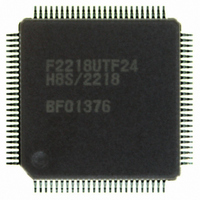
Manufacturer Part Number
HD64F2218UTF24
Description
IC H8S MCU FLASH 128K 100-TQFP
Manufacturer
Renesas Electronics America
Series
H8® H8S/2200r
Specifications of HD64F2218UTF24
Core Processor
H8S/2000
Core Size
16-Bit
Speed
24MHz
Connectivity
SCI, SmartCard, USB
Peripherals
DMA, POR, PWM, WDT
Number Of I /o
69
Program Memory Size
128KB (128K x 8)
Program Memory Type
FLASH
Ram Size
12K x 8
Voltage - Supply (vcc/vdd)
2.7 V ~ 3.6 V
Data Converters
A/D 6x10b
Oscillator Type
Internal
Operating Temperature
-20°C ~ 75°C
Package / Case
100-TQFP, 100-VQFP
For Use With
3DK2218-SS - KIT DEV H8S/2218 WINDOWS SIDESHW
Lead Free Status / RoHS Status
Contains lead / RoHS non-compliant
Eeprom Size
-
Available stocks
Company
Part Number
Manufacturer
Quantity
Price

Part Number:
HD64F2218UTF24V
Manufacturer:
RENESAS/瑞萨
Quantity:
20 000


4.1
As table 4.1 indicates, exception handling may be caused by a reset, trace, trap instruction, or
interrupt. Exception handling is prioritized as shown in table 4.1. If two or more exceptions occur
simultaneously, they are accepted and processed in order of priority. Exception sources, the stack
structure, and operation of the CPU vary depending on the interrupt control mode. For details on
the interrupt control mode, refer to section 5, Interrupt Controller.
Table 4.1
Note:
4.2
Different vector addresses are assigned to different exception sources. Table 4.2 lists the exception
sources and their vector addresses. Since the usable modes differ depending on the product, for
details on each product, refer to section 3, MCU Operating Modes.
Priority
High
Low
*
Exception Handling Types and Priority
Exception Sources and Exception Vector Table
Supported only by the H8S/2218 Group.
Exception Type
Reset
Trace
Interrupt
Trap instruction
(TRAPA)
Exception Types and Priority
Section 4 Exception Handling
Start of Exception Handling
Starts immediately after a low-to-high transition at the RES or
MRES* pin, or when the watchdog timer overflows. The CPU
enters the reset state when the RES pin is low. The CPU enters
the manual reset state when the MRES pin* is low.
Starts when execution of the current instruction or exception
handling ends, if the trace (T) bit in the EXR is set to 1. This is
enabled only in trace interrupt control mode 2. Trace exception
processing is not performed after RTE instruction execution.
Starts when execution of the current instruction or exception
handling ends, if an interrupt request has been issued. Note that
after executing the ANDC, ORC, XORC, or LDC instruction or at
the completion of reset exception processing, no interrupt is
detected.
Started by execution of a trap instruction (TRAPA). Trap exception
processing is always accepted in program execution state.
Rev.7.00 Dec. 24, 2008 Page 81 of 698
REJ09B0074-0700
Related parts for HD64F2218UTF24
Image
Part Number
Description
Manufacturer
Datasheet
Request
R

Part Number:
Description:
KIT STARTER FOR M16C/29
Manufacturer:
Renesas Electronics America
Datasheet:

Part Number:
Description:
KIT STARTER FOR R8C/2D
Manufacturer:
Renesas Electronics America
Datasheet:

Part Number:
Description:
R0K33062P STARTER KIT
Manufacturer:
Renesas Electronics America
Datasheet:

Part Number:
Description:
KIT STARTER FOR R8C/23 E8A
Manufacturer:
Renesas Electronics America
Datasheet:

Part Number:
Description:
KIT STARTER FOR R8C/25
Manufacturer:
Renesas Electronics America
Datasheet:

Part Number:
Description:
KIT STARTER H8S2456 SHARPE DSPLY
Manufacturer:
Renesas Electronics America
Datasheet:

Part Number:
Description:
KIT STARTER FOR R8C38C
Manufacturer:
Renesas Electronics America
Datasheet:

Part Number:
Description:
KIT STARTER FOR R8C35C
Manufacturer:
Renesas Electronics America
Datasheet:

Part Number:
Description:
KIT STARTER FOR R8CL3AC+LCD APPS
Manufacturer:
Renesas Electronics America
Datasheet:
Part Number:
Description:
KIT STARTER FOR RX610
Manufacturer:
Renesas Electronics America
Datasheet:

Part Number:
Description:
KIT STARTER FOR R32C/118
Manufacturer:
Renesas Electronics America
Datasheet:

Part Number:
Description:
KIT DEV RSK-R8C/26-29
Manufacturer:
Renesas Electronics America
Datasheet:

Part Number:
Description:
KIT STARTER FOR SH7124
Manufacturer:
Renesas Electronics America
Datasheet:

Part Number:
Description:
KIT STARTER FOR H8SX/1622
Manufacturer:
Renesas Electronics America
Datasheet:

Part Number:
Description:
KIT DEV FOR SH7203
Manufacturer:
Renesas Electronics America
Datasheet: